Content .. 1496 1497 1498 1499 ..
Mitsubishi Galant (2004+). Manual - part 1498
MULTI-CENTER DISPLAY
TSB Revision
CHASSIS ELECTRICAL
54A-235
• The fail-safe function will be deactivated if its internal
temperature has reduced to 85
°C (185°F) or less, or the
ignition switch is turned to the "LOCK" (OFF) position.
DIAGNOSIS FUNCTION
M1543007000465
ON-BOARD DIAGNOSTICS
The multi-center display (middle grade type) moni-
tors its input/output signals (some signals all the time
and others under specified conditions). When an
irregular signal is initially monitored, the multi-center
display (middle grade type) decides that a malfunc-
tion has occurred and records the occurrence as a
diagnostic trouble code. There are 9 diagnostic
items. The diagnostic results can be read with a scan
tool MB991958 (MUT-III sub assembly). Diagnostic
trouble codes are kept in memory by direct battery
feed. The codes are retained in memory even if the
ignition switch is in the "LOCK" (OFF) position. Diag-
nostic trouble codes will, however, be erased when a
battery terminal or the multi-center display (middle
grade type) connector is disconnected. In addition,
the diagnostic trouble code can also be erased by
scan tool MB991958 (MUT-III sub assembly).
NOTE: If a connector or sensor is disconnected
when the ignition switch is in the "ON" position, a
diagnostic trouble code is stored in memory. In this
case, erase the DTC using the scan tool.
NOTE: The 9 diagnostic items are displayed in
numeric order.
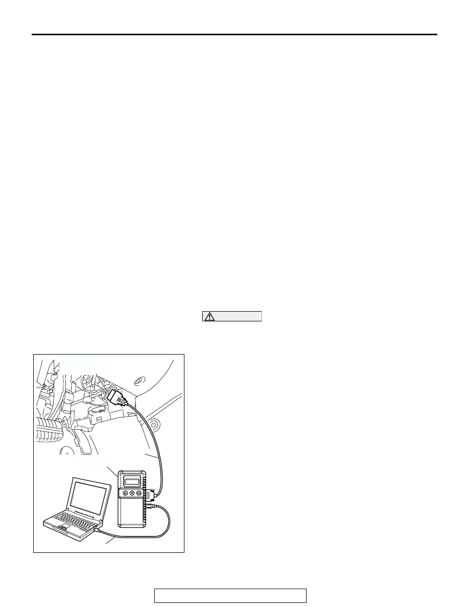
HOW TO CONNECT SCAN TOOL (MUT-III)
Required Special Tools:
• MB991958: Scan Tool (MUT-III Sub Assembly)
• MB991824: Vehicle Communication Interface (V.C.I.)
• MB991827: MUT-III USB Cable
• MB991911: MUT-III Main Harness A (Vehicles with CAN
communication system)
CAUTION
To prevent damage to scan tool MB991958, always turn the
ignition switch to the "LOCK" (OFF) position before con-
necting or disconnecting scan tool MB991958.
1. Ensure that the ignition switch is at the "LOCK" (OFF)
position.
2. Start up the personal computer.
3. Connect special tool MB991827 to special tool MB991824
and the personal computer.
4. Connect special tool MB991910 to special tool MB991824.
5. Connect special tool MB991910 to the data link connector.
6. Turn the power switch of special tool MB991824 to the "ON"
position.
NOTE: When special tool MB991824 is energized, special
tool MB991824 indicator light will be illuminated in a green
color.
7. Start the MUT-III system on the personal computer.
NOTE: Disconnecting the scan tool MB991958 is the
reverse of the connecting sequence, making sure that the
ignition switch is at the "LOCK" (OFF) position.
AC305412
AB
MB991910
DATA LINK
CONNECTOR
MB991824
MB991827