Mitsubishi Galant. Manual - part 699
SWS DIAGNOSIS
TSB Revision
SIMPLIFIED WIRING SYSTEM (SWS)
54B-191
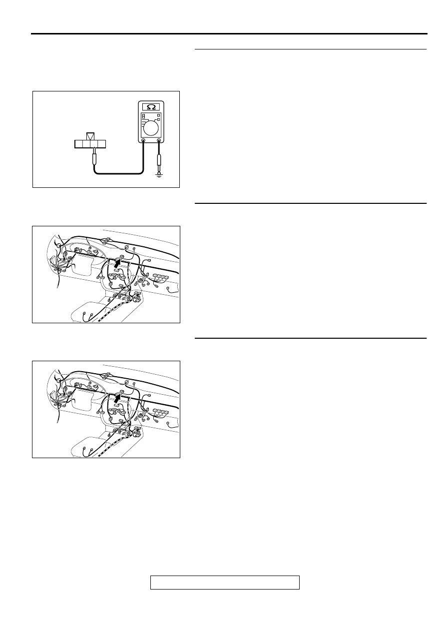
STEP 2. Check the hazard warning light switch ground
circuit at the hazard warning light switch connector C-07.
(1)Disconnect the hazard warning light switch connector C-07
and measure at the harness side.
(2)Measure the resistance between terminal 2 and ground.
Q: Is the resistance less than 2 ohm?
YES : Go to Step 5.
NO : Go to Step 3.
STEP 3. Check hazard warning light switch connector C-07
for damage.
Q: Is hazard warning light switch connector C-07 in good
condition?
YES : Go to Step 4.
NO : Repair or replace it. Refer to GROUP 00E, Harness
Connector Inspection
. The hazard warning
light switch input signal should be able to be checked
and the functions, which are described in the
"Technical Description (comment)," should work
normally.
STEP 4. Check the harness wire between hazard warning
light switch connector C-07 and ground.
Q: Is the harness wire between hazard warning light switch
connector C-07 and ground in good condition?
YES : There is no action to be taken.
NO : Repair it. The hazard warning light switch input signal
should be able to be checked and the functions,
which are described in the "Technical Description
(comment)," should work normally.
4 3 2 1
AC002151AB
CONNECTOR C-07
(HARNESS SIDE)
AC003089 AJ
CONNECTOR: C-07
AC003089 AJ
CONNECTOR: C-07