Mitsubishi Galant 9G. Manual - part 536


  Index      Mitsubishi     Mitsubishi Galant 9G - service repair manual


Search            


Content   ..  534  535  536  537   ..


Mitsubishi Galant 9G. Manual - part 536


AUTOMATIC TRANSAXLE DIAGNOSIS

TSB Revision

AUTOMATIC TRANSAXLE

23A-222

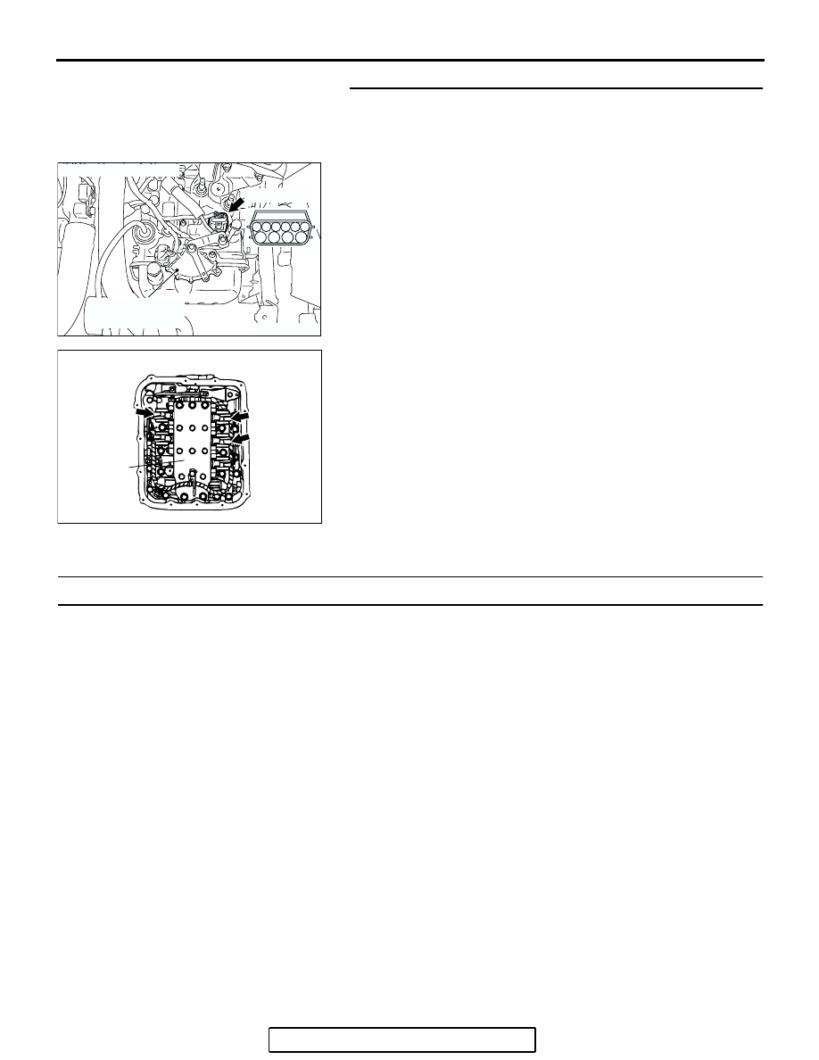
STEP 13. Check the harness for an open or short circuit to 
ground between A/T control solenoid valve assembly 
connector B-108 (terminals 3, 4, 5, and 9) and solenoid 
valve connectors B-108-1, B-108-2 and B-108-3.
Q: Is the harness wire in good condition?

YES : Replace the PCM.
NO :  Replace the harness wire.

DTC 34 (P0768): Overdrive Solenoid Valve System

.

SOLENOID VALVE SYSTEM CIRCUIT

 Refer to 

P.23A-187

.

.

CIRCUIT OPERATION

 Refer to 

P.23A-187

.

.

DESCRIPTIONS OF MONITOR METHODS

• If solenoid terminal voltage is below specified 

value when shift control is not in progress, PCM 
judges that overdrive solenoid valve has a failure.

.

MONITOR EXECUTION

• Continuous

.

MONITOR EXECUTION CONDITIONS 
(OTHER MONITOR AND SENSOR)

Other Monitor (There is no temporary DTC stored 

in memory for the item monitored below)

• DTC 41 (P0731): 1st gear incorrect ratio

• DTC 42 (P0732): 2nd gear incorrect ratio

• DTC 43 (P0733): 3rd gear incorrect ratio

• DTC 44 (P0734): 4th gear incorrect ratio

• DTC 46 (P0736): Reverse gear incorrect ratio

• DTC 36 (P0743): Torque converter clutch sole-

noid malfunction

• DTC 31 (P0753): Low-reverse solenoid malfunc-

tion

• DTC 32 (P0758): Underdrive solenoid malfunc-

tion

• DTC 33 (P0763): Second solenoid malfunction

• DTC 54 (P1751): A/T control relay malfunction

Sensor (The sensor below is determined to be 

normal)

• Torque converter clutch solenoid

• Low-reverse solenoid

• Underdrive solenoid

• Second solenoid

• A/T control relay

AC306322

CONNECTOR: B-108

B-108 (GR)

AC

TRANSMISSION
RANGE SWITCH

2

7

1

8

3

9

4

6

10

5

AC002219

CONNECTORS: B-108-1, B-108-2, B-108-3     

CD

B-108-1

B-108-2

B-108-3

VALVE BODY
ASSEMBLY

AUTOMATIC TRANSAXLE DIAGNOSIS

TSB Revision

AUTOMATIC TRANSAXLE

23A-223

.

LOGIC FLOW CHARTS (Monitor Sequence)

.

DTC SET CONDITIONS

Check Conditions

• Solenoid status: either solid ON or OFF.

• Shift status: in-gear.

• Voltage of battery: 10 volts or more.

Judgement Criteria

• Solenoid voltage: 3 volts or less. (0.3 second)

• If DTC 34 (P0768) is set consecutively four times, 

the transaxle is locked into 3rd gear as a fail-safe 
measure, and the "N" range light flashes once 
per second.

.

OBD-II DRIVE CYCLE PATTERN

Start the engine, and keep the vehicle stopped in "P" 
range for 5 seconds.

.

TROUBLESHOOTING HINTS (THE MOST 
LIKELY CAUSES FOR THIS CODE TO BE 
SET ARE:)

• Malfunction of the overdrive solenoid valve

• Damaged harness or connector

• Malfunction of the PCM

AC205284

Good

Malfunction

END

START

In-gear?

Shift solenoid-D is in ON 
or OFF steady state

Voltage of battery > 10 V

Solenoid circuit 
voltage < 3 V

Continuous failure 
for 0.3 sec.

Yes

No

Yes

No

Yes

No

Yes

No

Yes

No

Overdrive solenoid valve is in 
    ON or OFF steady state

AB

AUTOMATIC TRANSAXLE DIAGNOSIS

TSB Revision

AUTOMATIC TRANSAXLE

23A-224

DIAGNOSIS

Required Special Tool:

• MB991958: Scan Tool (MUT-III Sub Assembly)

• MB991824: V.C.I.

• MB991827: MUT-III USB Cable

• MB991910: MUT-III Main Harness A

STEP 1. Using scan tool MB991958, check actuator test 
item 04: Overdrive Solenoid Valve.

CAUTION

To prevent damage to scan tool MB991958, always turn the 
ignition switch to the "LOCK" (OFF) position before con-
necting or disconnecting scan tool MB991958.
(1) Connect scan tool MB991958 to the data link connector.
(2) Turn the ignition switch to the "ON" position.
(3) Set scan tool MB991958 to the actuator test mode.

• Item 04: Overdrive Solenoid Valve.

• An audible clicking or buzzing should be heard when 

the overdrive solenoid valve is energized.

(4) Turn the ignition switch to the "LOCK" (OFF) position.
Q: Is the solenoid valve operating properly?

YES : It can be assumed that this malfunction is intermittent. 

Refer to GROUP 00, How to Use 
Troubleshooting/Inspection Service Points 

− How to 

Cope with Intermittent Malfunctions 

P.00-14

.

NO :  Go to Step 2.

AC305412

AB

MB991910

DATA LINK

CONNECTOR

MB991824

MB991827

AUTOMATIC TRANSAXLE DIAGNOSIS

TSB Revision

AUTOMATIC TRANSAXLE

23A-225

STEP 2. Using scan tool MB991958, read the A/T 
diagnostic trouble code.
(1) Connect scan tool MB991958 to the data link connector.
(2) Turn the ignition switch to the "ON" position.
(3) Check for A/T diagnostic trouble code.
(4) Turn the ignition switch to the "LOCK" (OFF) position.
Q: Is DTC 54 set? (DTC 54 may be set along with multiple 

DTCs).
YES : 
Refer to 

P.23A-267

 DTC 54: A/T Control Relay 

System.

NO :  Go to Step 3.

STEP 3. Using scan tool MB991958, read the A/T 
diagnostic trouble code.
(1) Connect scan tool MB991958 to the data link connector.
(2) Turn the ignition switch to the "ON" position.
(3) Check for A/T diagnostic trouble code.
(4) Turn the ignition switch to the "LOCK" (OFF) position.
Q: Are DTC 32 and DTC 33 set? (Multiple DTCs may be set).

YES : Go to Step 8.
NO :  Go to Step 4.

AC305412

AB

MB991910

DATA LINK

CONNECTOR

MB991824

MB991827

AC305412

AB

MB991910

DATA LINK

CONNECTOR

MB991824

MB991827


Content   ..  534  535  536  537   ..