Mitsubishi Galant 9G. Manual - part 467


  Index      Mitsubishi     Mitsubishi Galant 9G - service repair manual


Search            


Content   ..  465  466  467  468   ..


Mitsubishi Galant 9G. Manual - part 467


EMISSION CONTROL

TSB Revision

ENGINE AND EMISSION CONTROL

17-86

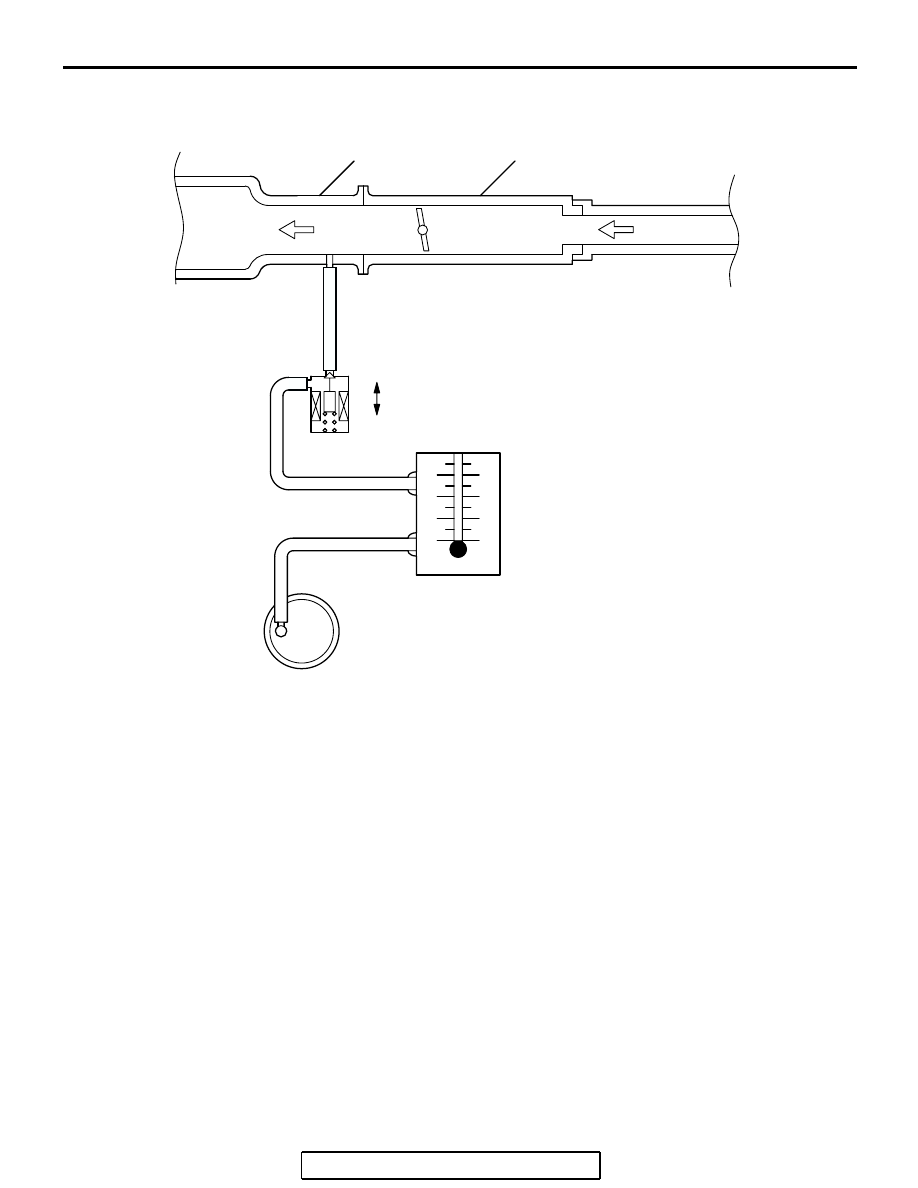
PURGE CONTROL SYSTEM CHECK (PURGE FLOW CHECK)

M1173001400620

Required Special Tool:
MB995061: Purge Flow Indicator
1. Disconnect the purge hose from the evaporative emission 

(EVAP) purge solenoid, and connect special tool MB995061 
between the EVAP purge solenoid and the purge hose.

2. Before inspection, set the vehicle in the following conditions:

• Engine coolant temperature: 80 − 95°C (176 − 203°F)

• Lights, electric cooling fan and accessories: OFF

• Transaxle: P range

NOTE: Vehicles for Canada, the headlight, taillight, etc. 
remain lit even when the lighting switch is in "OFF" position 
but this is no problem for checks.

3. Run the engine at idle for more than four minutes.
4. Check the purge flow volume when engine is revved 

suddenly several times.

Standard value: Momentarily 20 cm

3

/s (2.5 SCFH) or 

more.

AK300556

THROTTLE BODY

INTAKE MANIFOLD

FROM 
AIR CLEANER

TO 
COMBUSTION
CHAMBER

AB

OFF

ON

EVAPORATIVE EMISSION 
PURGE SOLENOID

(ON: OPENED)

PURGE
FLOW
INDICATOR
(MB995061)

PURGE HOSE

EVAPORATIVE EMISSION 
CANISTER

EMISSION CONTROL

TSB Revision

ENGINE AND EMISSION CONTROL

17-87

5. If the purge flow volume is less than the standard value, 

check it again with the vacuum hose disconnected from the 
EVAP canister. If the purge flow volume is less than the 
standard value, check the vacuum port and the vacuum 
hose for clogging. Also check the EVAP purge solenoid. If 
the purge flow volume is at the standard value, replace the 
EVAP canister.

EVAPORATIVE EMISSION PURGE SOLENOID 
CHECK

M1173001700289

1. Disconnect the vacuum hose (black, black with red paint 

mark) from the evaporative emission (EVAP) purge 
solenoid.
NOTE: When disconnecting the vacuum hose, always place 
an identification mark so that it can be reconnected at its 
original position.

2. Disconnect the harness connector.
3. Connect a hand vacuum pump to nipple (A) of the EVAP 

purge solenoid (refer to the illustration at left).

4. As described in the chart below, check airtightness by 

applying a vacuum with voltage applied directly from the 
battery to the EVAP purge solenoid valve and without 
applying voltage.

5. Measure the resistance between the terminals of the EVAP 

purge solenoid.

Standard value: 22 

 26  [at 20°C (68°F)]

6. Replace the solenoid if resistance is out of specification.

MASS AIRFLOW  SENSOR CHECK

M1173050400053

<2.4L ENGINE>

To inspect these parts, refer to GROUP 13A, Multiport Fuel 
Injection (MFI) <2.4L Engine> 

− Multiport Fuel Injection (MFI) 

Diagnosis 

− Diagnostic Trouble Code Chart 

P.13A-33

.

<3.8L ENGINE>

To inspect these parts, refer to GROUP 13B, Multiport Fuel 
Injection (MFI) <3.8L Engine> 

− Multiport Fuel Injection (MFI) 

Diagnosis 

− Diagnostic Trouble Code Chart 

P.13B-34

.

BATTERY POSITIVE 
VOLTAGE

NORMAL CONDITION

Applied

Vacuum leaks

Not applied

Vacuum maintained

AK200339AB

A

B

AK103872

EMISSION CONTROL

TSB Revision

ENGINE AND EMISSION CONTROL

17-88

BAROMETRIC PRESSURE SENSOR CHECK

M1173008000269

<2.4L ENGINE>

To inspect the sensor, refer to GROUP 13A, Multiport Fuel 
Injection (MFI) <2.4L Engine> 

− Multiport Fuel Injection (MFI) 

Diagnosis 

− Diagnostic Trouble Code Chart 

P.13A-33

.

<3.8L ENGINE>

To inspect the sensor, refer to GROUP 13B, Multiport Fuel 
Injection (MFI) <3.8L Engine> 

− Multiport Fuel Injection (MFI) 

Diagnosis 

− Diagnostic Trouble Code Chart 

P.13B-34

.

ENGINE COOLANT TEMPERATURE SENSOR 
CHECK

M1173008100523

<2.4L ENGINE>

To inspect the sensor, refer to GROUP 13A, Multiport Fuel 
Injection (MFI) <2.4L Engine> 

− Multiport Fuel Injection (MFI) 

Diagnosis 

− Diagnostic Trouble Code Chart 

P.13A-33

.

<3.8L ENGINE>

To inspect the sensor, refer to GROUP 13B, Multiport Fuel 
Injection (MFI) <3.8L Engine> 

− Multiport Fuel Injection (MFI) 

Diagnosis 

− Diagnostic Trouble Code Chart 

P.13B-34

.

INTAKE AIR TEMPERATURE SENSOR CHECK

M1173008200263

<2.4L ENGINE>

To inspect the sensor, refer to GROUP 13A, Multiport Fuel 
Injection (MFI) <2.4L Engine> 

− Multiport Fuel Injection (MFI) 

Diagnosis 

− Diagnostic Trouble Code Chart 

P.13A-33

.

<3.8L ENGINE>

To inspect the sensor, refer to GROUP 13B, Multiport Fuel 
Injection (MFI) <3.8L Engine> 

− Multiport Fuel Injection (MFI) 

Diagnosis 

− Diagnostic Trouble Code Chart 

P.13B-34

.

FUEL TANK DIFFERENTIAL PRESSURE SENSOR 
CHECK

M1173007700221

To inspect the sensor, refer to GROUP 13C, Fuel Supply 

− Fuel 

Tank 

− Fuel Tank Inspection − Fuel Tank Differential Pressure 

Sensor Check 

P.13C-16

.

EVAPORATIVE EMISSION VENTILATION 
SOLENOID CHECK

M1173007800206

Refer to Emission Control 

− Evaporative Emission Canister and 

Fuel Tank Pressure Relief Valve 

− Inspection − Evaporative 

Emission Ventilation Solenoid Check 

P.17-96

.

EMISSION CONTROL

TSB Revision

ENGINE AND EMISSION CONTROL

17-89

EXHAUST GAS RECIRCULATION (EGR) SYSTEM

GENERAL DESCRIPTION (EXHAUST GAS RECIRCULATION SYSTEM)

M1173005200554

The exhaust gas recirculation system (EGR) lowers 
the nitrogen oxides (NOx) emission level. When the 
air/fuel mixture combustion temperature is high, a 
large quantity of NOx is generated in the combustion 
chamber. Therefore, this system recirculates part of 
exhaust gas from the exhaust port of the cylinder 
head to the combustion chamber through the intake 
manifold to decrease the air/fuel mixture combustion 
temperature, resulting in reduction of NOx. The EGR 
flow rate is controlled by the EGR valve (Stepper 
Motor) for driveability quality.

OPERATION

When the engine coolant temperature is low, when 
the engine is at idle or when a wide open throttle 
operation is performed, the EGR valve (Stepper 
Motor) is kept closed, achieving no EGR. After warm-
ing up of the engine, the EGR valve (Stepper Motor) 
can be opened by the powertrain control module 
(PCM).
The PCM monitors the EGR system and illuminates 
the Malfunction Indicator Lamp (SERVICE ENGINE 
SOON or Check Engine Lamp) to indicate that there 
is a malfunction.

SYSTEM DIAGRAM
<2.4L ENGINE>

AK300557 AD

MASS AIRFLOW SENSOR

ENGINE COOLANT
TEMPERATURE SENSOR

CRANKSHAFT POSITION
SENSOR

PCM

MFI RELAY

BATTERY

EGR VALVE

(STEPPER MOTOR)


Content   ..  465  466  467  468   ..