Mitsubishi Galant 9G. Manual - part 164
CENTRALIZED JUNCTION
TSB Revision
CIRCUIT DIAGRAMS
90-18
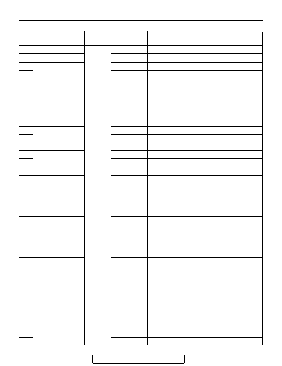
PASSENGER COMPARTMENT
NO. POWER SUPPLY
CIRCUIT
NAME
RATED
CAPACITY (A)
HOUSING
COLOR
LOAD CIRCUIT
1
−
Fuse
−
−
−
2
−
−
−
−
3
Fusible link No.5
20
Yellow
Audio amplifier
4
20
Yellow
Sunroof assembly
5
Fusible link No.1
30
Green
Capacitor and rear window defogger
6
30
Green
Blower motor and resistor
7
−
−
−
8
−
−
−
9
15
Blue
Accessory socket
10
15
Blue
Data link connector and ETACS-ECU
11
Ignition switch (ACC)
15
Blue
ETACS-ECU
12
−
−
−
13
Ignition switch (IG2)
7.5
Brown
Sunroof assembly
14
Ignition switch (ACC)
7.5
Brown
Remote controlled mirror
15
−
−
−
16
−
−
−
17
Ignition switch (IG1)
7.5
Brown
Fuel pump relay and powertrain
control module
18
Ignition switch (ACC)
−
−
−
19
Fusible link No.1
(Fuse No.5 in junction
block)
7.5
Brown
Remote controlled mirror (mirror
heater)
20
Ignition switch (IG2)
7.5
Brown
A/C compressor clutch relay,
A/C-ECU, blower relay, condenser
fan motor, fan control relay,
front-ECU, heated seat relay,
outside/inside air selection damper
control motor, radiator fan relay and
rear window defogger relay
21
Ignition switch (IG1)
−
−
−
22
7.5
Brown
A/T control relay, air bag off indicator
light (passenger’s side), input shaft
speed sensor, occupant
classification-ECU, output shaft
speed sensor, powertrain control
module, rear combination light, seat
belt warning light (passenger’s side)
and SRS-ECU
23
7.5
Brown
ABS-ECU, ABS/TCL-ECU, column
switch, combination meter,
ETACS-ECU, multi-center display unit
and SRS-ECU
24
10
Red
Ignition coil