Mitsubishi Galant 9G. Manual - part 1627


  Index      Mitsubishi     Mitsubishi Galant 9G - service repair manual


Search            


Content   ..  1625  1626  1627  1628   ..


Mitsubishi Galant 9G. Manual - part 1627


ANTI-LOCK BRAKING SYSTEM (ABS) DIAGNOSIS

TSB Revision

ANTI-LOCK BRAKING SYSTEM (ABS)

35B-92

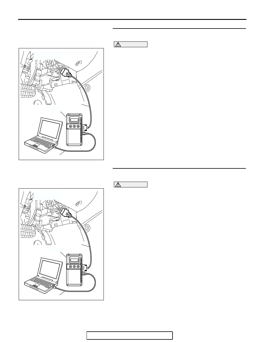
STEP 1. Using scan tool MB991958, diagnose the CAN bus 
line.

CAUTION

To prevent damage to scan tool MB991958, always turn the 
ignition switch to the "LOCK" (OFF) position before con-
necting or disconnecting scan tool MB991958.
Use scan tool MB991958 to diagnose the CAN bus lines.
(1) Connect scan tool MB991958 to the data link connector.
(2) Turn the ignition switch to the "ON" position.
(3) Diagnose the CAN bus line.
Q: Is the check result satisfactory?

YES : Go to Step 2.
NO :  Repair the CAN bus lines (Refer to GROUP 54C, 

Diagnosis-CAN Bus Diagnostic Chart 

P.54C-14

). 

Repair the CAN bus lines, and then go to Step 2.

STEP 2. Using scan tool MB991958, read the combination 
meter diagnostic trouble code.

CAUTION

To prevent damage to scan tool MB991958, always turn the 
ignition switch to the "LOCK" (OFF) position before con-
necting or disconnecting scan tool MB991958.
Use scan tool MB991958 to check whether combination meter 
DTC U1102 has been set.
(1) Connect scan tool MB991958 to the data link connector.
(2) Turn the ignition switch to the "ON" position.
(3) Check whether combination meter DTC U1102 has been 

set.

Q: Is combination meter DTC U1102 set?

YES : Replace the hydraulic unit (integrated with 

ABS-ECU). 

NO :  Replace the combination meter.

AC305412

AB

MB991910

DATA LINK

CONNECTOR

MB991824

MB991827

AC305412

AB

MB991910

DATA LINK

CONNECTOR

MB991824

MB991827

ANTI-LOCK BRAKING SYSTEM (ABS) DIAGNOSIS

TSB Revision

ANTI-LOCK BRAKING SYSTEM (ABS)

35B-93

INSPECTION PROCEDURE 5: Faulty ABS Operation

.

TECHNICAL DESCRIPTION (COMMENT)

The cause depends on driving and road surface con-
ditions, so diagnosis may be difficult. However, if no 
diagnostic trouble code is displayed, carry out the fol-
lowing inspection.

.

TROUBLESHOOTING HINTS (The most 
likely causes for this case:)

• Malfunction of the hydraulic unit

.

DIAGNOSIS

STEP 1. Hydraulic unit check
 Refer to 

P.35B-102

.

Q: Is the hydraulic unit normal?

YES : Go to Step 2.
NO :  Connect the brake pipes correctly, repair the external 

brake lines, or replace the hydraulic unit.

STEP 2. Verify that the condition described by the 
customer exists.
Q: Can any faults be found with the brake operation?

YES : Check the brake system related components except 

the ABS system.

NO :  The procedure is complete.

ANTI-LOCK BRAKING SYSTEM (ABS) DIAGNOSIS

TSB Revision

ANTI-LOCK BRAKING SYSTEM (ABS)

35B-94

DATA LIST REFERENCE TABLE

M1352011500780

The following items can be read by the scan tool 
from the ABS-ECU input data.

ACTUATOR TEST REFERENCE TABLE

M1352011600765

The scan tool activates the following actuators for 
testing.
NOTE: If the ABS-ECU runs down, actuator testing 
cannot be carried out.

NOTE: Actuator testing is only possible when the 
vehicle is stationary.

.

MUT-III 
SCAN TOOL 
DISPLAY

ITEM 
NO.

CHECK ITEM

CHECKING REQUIREMENTS NORMAL 

VALUE

FR wheel 
speed sensor

01

Front-right wheel speed sensor Drive the vehicle

Vehicle speeds 
displayed on the 
speedometer 
and scan tool are 
identical.

FL wheel 
speed sensor

02

Front-left wheel speed sensor

RR wheel 
speed sensor

03

Rear-right wheel speed sensor

RL wheel 
speed sensor

04

Rear-left wheel speed sensor

Battery 
voltage

05

ABS-ECU power supply voltage Ignition switch power supply 

voltage and valve monitor 
voltage

Battery positive 
voltage

Stop light 
switch

06

Stoplight switch

Depress the brake pedal.

ON

Release the brake pedal.

OFF

TCL mode

35

TCL operation

When the TCL outputs the 
operation permission signal 
during driving

ON

When the TCL outputs the 
operation inhibition signal 
during driving

OFF

Under 
cranking

40

Engine cranking operation

When cranking an engine up

No

When not cranking an engine 
up

Yes

ANTI-LOCK BRAKING SYSTEM (ABS) DIAGNOSIS

TSB Revision

ANTI-LOCK BRAKING SYSTEM (ABS)

35B-95

ACTUATOR TEST SPECIFICATIONS

CHECK AT  ABS-ECU

M1352011800769

.

TERMINAL VOLTAGE CHECK CHART

Required Special Tool:
MB991970: ABS Check Harness
1. Disconnect the ABS-ECU connector A-02, and then use 

special tool MB991970 to measure the voltages between 
terminals (2) and each terminal other than terminal (18). 
Also measure voltages between terminal (18) and each 
terminal other than terminal (2).

NOTE: Do not measure terminal voltage for approximately 
three seconds after the ignition switch is turned "ON." The 
ABS-ECU performs the initial check during that period.

NO.

ITEM

PARTS TO BE 
ACTIVATED

01

FR wheel speed sensor Solenoid valves and 

pump motors in the 
hydraulic unit (simple 
inspection mode)

02

FL wheel speed sensor

03

RR wheel speed sensor

04

RL wheel speed sensor

09

Engine TCL Drive

Outputs the engine 
torque control signal 
(engine torque = 0) to 
PCM for three seconds.

AC100172 AI

ACTIVATION PATTERN

A

B

C

SOLENOID
VALVE

END OF
FORCED
ACTION

START OF
FORCED
ACTION

1 s

2 s

PUMP
MOTOR

ON

OFF

NOTE
A:
B:
C:

HYDRAULIC PRESSURE INCREASES
HYDRAULIC PRESSURE HOLDS
HYDRAULIC PRESSURE DECREASES

APPROXIMATELY
0.05 s

APPROXIMATELY
0.01 s

AC211156 AB

ABS-ECU

A-02 HARNESS CONNECTOR

MB991970

INSPECTION
HARNESS
CONNECTOR


Content   ..  1625  1626  1627  1628   ..