Content .. 1482 1483 1484 1485 ..
Mitsubishi Galant 9G. Manual - part 1484
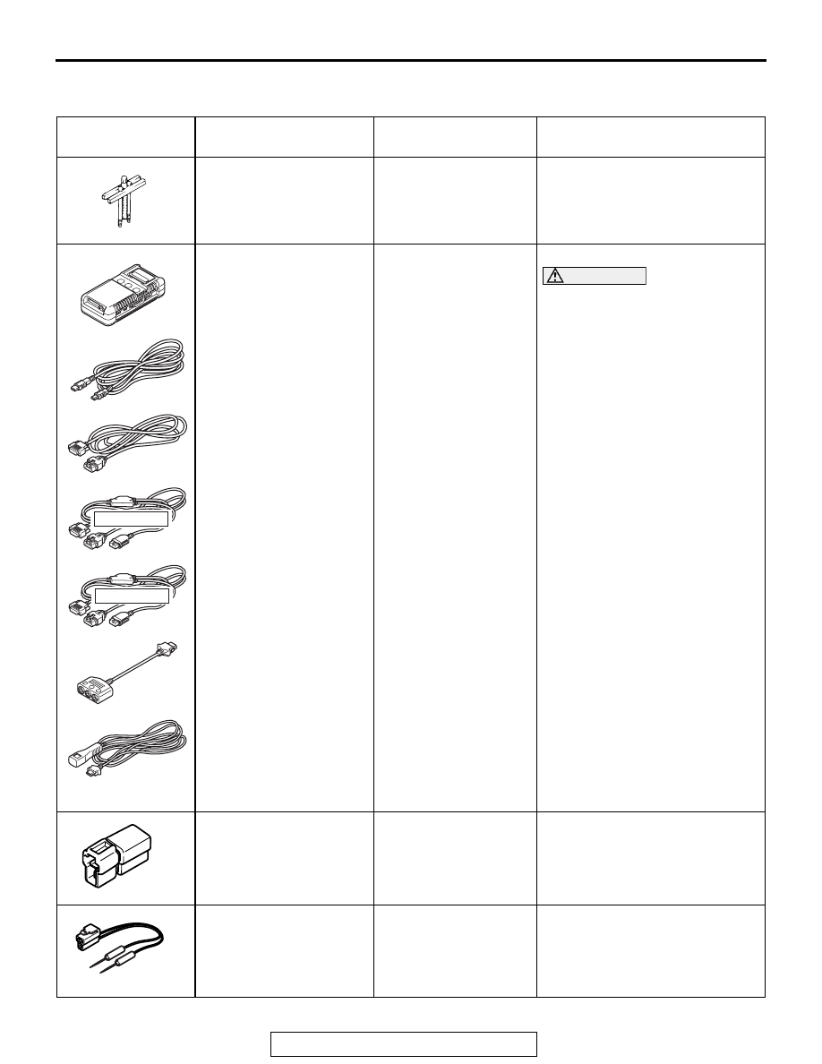
SPECIAL TOOLS
TSB Revision
SUPPLEMENTAL RESTRAINT SYSTEM (SRS)
52B-346
SPECIAL TOOLS
M1524000700453
TOOL
TOOL NUMBER AND
NAME
SUPERSESSION
APPLICATION
MB990803
Steering wheel puller
General service tool
Steering wheel removal
MB991958
A: MB991824
B: MB991827
C: MB991910
D: MB991911
E: MB991914
F: MB991825
G: MB991826
Scan tool (MUT-III sub
assembly)
A: Vehicle
communication
interface (V. C. I.)
B: MUT-III USB cable
C: MUT-III main harness
A (Vehicles with CAN
communication
system)
D: MUT-III main harness
B (Vehicles without
CAN communication
system)
E: MUT-III main harness
C (for Daimler Chrysler
models only)
F: MUT-III measurement
adapter
G: MUT-III trigger
harness
MB991824-KIT
NOTE: G: MB991826
MUT-III Trigger
Harness is not
necessary when
pushing V.C.I. ENTER
key.
Checking diagnostic trouble code
CAUTION
For vehicles with CAN
communication, use MUT-III
main harness A to send
simulated vehicle speed. If you
connect MUT-III main harness
B instead, the CAN
communication does not
function correctly.
MB991865
Dummy resistor
SRS air bag and seat belt with
pre-tensioner circuit check
MB991866
Resistor harness
SRS air bag circuit check
MB990803AB
MB991910
MB991826
MB991958
MB991911
MB991914
MB991824
MB991827
MB991825
DO NOT USE
A
B
C
D
E
F
G
DO NOT USE
MB991865
MB991866