Content .. 1315 1316 1317 1318 ..
Mitsubishi Galant 9G. Manual - part 1317
DIAGNOSIS
TSB Revision
CONTROLLER AREA NETWORK (CAN)
54C-372
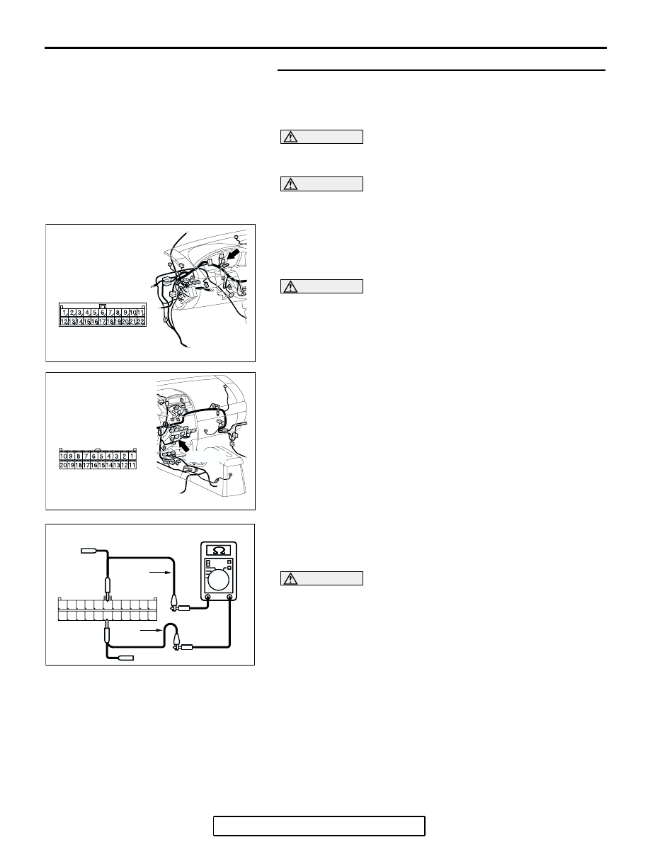
STEP 14. Check the CAN_L and H lines (communication
lines only) between joint connector (3) and the A/C-ECU for
a short circuit. Measure the resistance at joint connector
(3) C-02.
CAUTION
A digital multimeter should be used. For details refer to
.
CAUTION
The test wiring harness should be used. For details refer to
.
(1) Disconnect joint connector (3) C-02 and A/C-ECU
connector C-15, and measure the resistance at the wiring
harness side of joint connector (3) C-02.
(2) Turn the ignition switch to the "LOCK" (OFF) position.
CAUTION
Disconnect the negative battery terminal. For details refer
to
(3) Disconnect the negative battery terminal.
(4) Measure the resistance between joint connector (3)
terminals 6 and 17.
OK: 1 k
Ω or more
CAUTION
Strictly observe the specified wiring harness repair proce-
dure. For details refer to
Q: Does the resistance measure 1 k
Ω or more?
YES : If the resistance measures 1 k
Ω or more, go to Step
NO : If the resistance measures less than 1 k
Ω, repair the
wiring harness between joint connector (3) and the
A/C-ECU connector.
AC305231AP
CONNECTOR: C-02
AC305233 AH
CONNECTOR: C-15
HARNESS SIDE
C-15 (B)
AC209438
AC209438
TEST
HARNESS
AS
TEST
HARNESS
1110 9 8 7 6 5 4 3 2 1
22 21201918 1716 15 14 1312
HARNESS SIDE: C-02