Mitsubishi Galant 9G. Manual - part 1209


  Index      Mitsubishi     Mitsubishi Galant 9G - service repair manual


Search            


Content   ..  1207  1208  1209  1210   ..


Mitsubishi Galant 9G. Manual - part 1209


MULTIPORT FUEL INJECTION (MFI) DIAGNOSIS

TSB Revision

MULTIPORT FUEL INJECTION (MFI) <3.8L ENGINE>

13B-1136

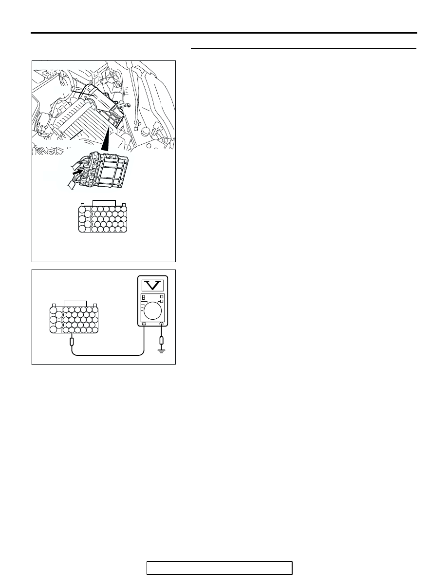
STEP 2. Check the circuit at PCM connector B-21.
(1) Disconnect the connectors B-21 and measure at the 

harness side.

(2) Turn the ignition switch to the "ON" position.

(3) Measure the voltage between terminal No. 81 and ground.

• Voltage should be battery positive voltage.

(4) Using a jumper wire, connect terminal No. 81 to ground.

• A/C compressor clutch relay should turn "ON".

(5) Turn the ignition switch to the "LOCK" (OFF) position.
Q: Is the voltage and A/C compressor relay condition 

normal?
YES : 
Replace the PCM. Then confirm that the malfunction 

sympton is eliminated.

NO :  Refer to GROUP 55, Diagnosis 

− Introduction To 

Heater, Air Conditioning And Ventilation Diagnosis 

P.55A-5

. Then confirm that the malfunction symptom 

is eliminated.

AK303018

55

56

54 53 52 51

57

62 61 60 59 58

63

69 68 67 66 65 64

70

75 74 73 72 71

76

82 81 80 79 78 77

83

CONNECTOR: B-21

PCM

AB

HARNESS CONNECTOR: 
COMPONENT SIDE

AIR CLEANER

B-21 (B)

55

56

54 53 52 51

57

62 61 60 59 58

63

69 68 67 66 65 64

70

75 74 73 72 71

76

82 81 80 79 78 77

83

AK303276

B-21 HARNESS 
CONNECTOR: 
COMPONENT SIDE

AB

MULTIPORT FUEL INJECTION (MFI) DIAGNOSIS

TSB Revision

MULTIPORT FUEL INJECTION (MFI) <3.8L ENGINE>

13B-1137

DATA LIST REFERENCE TABLE

M1131152001578

CAUTION

• When shifting the selector lever to D range, the brakes should be applied so that the vehicle does 

not move forward.

• Driving tests always need two persons: one driver and one observer.

NOTE: Sensor 1 indicates the sensor mounted at a position closest to the engine, and sensor 2 indicates the 
sensor mounted at the position second close to the engine.
NOTE: Bank 1 indicates the right bank cylinder, and bank 2 indicates the left bank cylinder
NOTE: *

1

: In a new vehicle [driven approximately 500 km (311 mile) or less], the mass airflow sensor output 

value is sometimes 10% higher than the standard value.
NOTE: *

2

: The injector drive time represents the time when the cranking speed is at 250 r/min or below when 

the power supply voltage is 11 volts.
NOTE: *

3

: In a new vehicle [driven approximately 500 km (311 mile) or less], the injector drive time is some-

times 10% longer than the standard time.
NOTE: *

4

: Applicable to GST

NOTE: *

5

: Vehicles for Canada, the headlight, taillight, etc. remain lit even when the lighting switch is in "OFF" 

position but this is no problem for checks.

MUT-III 
SCAN TOOL 
DISPLAY

ITEM 
NO. 

INSPECTION ITEM

INSPECTION REQUIREMENT

NORMAL 
CONDITION

INSPECTION 
PROCEDURE 
NO.

REFERENCE 
PAGE

A/C 
RELAY

49

A/C 
compressor 
clutch relay

• Engine: warming up, idling

• A/C switch: "OFF"

OFF

Procedure 
No. 32

P.13B-113
4

• Engine: 

warming up, 
idling

• A/C switch: 

"ON"

A/C 
compressor 
clutch is not 
operating

OFF

A/C 
compressor 
clutch is 
operating

ON

APP SNS 
(MAIN)

78

Accelerator 
pedal position 
sensor (main)

Ignition switch: 
"ON"

Release the 
accelerator 
pedal

735 

− 1,335 

mV

Code No. 
P2122, 
P2123

P.13B-938

P.13B-948

Depress the 
accelerator 
pedal gradually

Increases in 
response to 
the pedal 
depression 
stroke

Depress the 
accelerator 
pedal fully

4,000 mV or 
more

MULTIPORT FUEL INJECTION (MFI) DIAGNOSIS

TSB Revision

MULTIPORT FUEL INJECTION (MFI) <3.8L ENGINE>

13B-1138

APP 
SNSR 
(SUB)

77

Accelerator 
pedal position 
sensor (sub)

Ignition switch: 
"ON"

Release the 
accelerator 
pedal

435 

− 1,035  

mV

Code No. 
P2127, 
P2128

P.13B-955

P.13B-965

Depress the 
accelerator 
pedal gradually

Increases in 
response to 
the pedal 
depression 
stroke

Depress the 
accelerator 
pedal fully

3,700 mV or 
more

BARO 
SENSOR

25

Barometric 
pressure 
sensor

Ignition switch: 
"ON"

At altitude of 0 
m (0 ft)

101 kPa 
(29.8 in.Hg)

Code No. 
P2228, 
P2229

P.13B-992

P.13B-994

At altitude of 
600 m (1,969 
ft)

95 kPa (28.1 
in.Hg)

At altitude of 
1,200 m (3,937 
ft)

88 kPa (26.0 
in.Hg)

At altitude of 
1,800 m (5,906 
ft)

81 kPa (23.9 
in.Hg)

BATT 
VOLTAGE

16

Power supply 
voltage

Ignition switch: "ON"

Battery 
positive 
voltage

Procedure 
No. 28

P.13B-109
6

CKP 
SENSOR

22

Crankshaft 
position sensor 

• Engine: cranking

• Tachometer: connected

Engine 
speeds 
displayed on 
the scan tool 
and 
tachometer 
are identical.

Code No. 
P0335

P.13B-604

Engine: idling

Engine coolant 
temperature is 
−20°C (−40°F)

1,300 

− 

1,500 r/min

Engine coolant 
temperature is 
0

°C (32°F)

1,300 

− 

1,500 r/min

Engine coolant 
temperature is 
20

°C (68°F)

1,300 

− 

1,500 r/min

Engine coolant 
temperature is 
40

°C (104°F)

1,040 

− 

1,240 r/min

Engine coolant 
temperature is 
80

°C (176°F)

580 

− 780 

r/min

MUT-III 
SCAN TOOL 
DISPLAY

ITEM 
NO. 

INSPECTION ITEM

INSPECTION REQUIREMENT

NORMAL 
CONDITION

INSPECTION 
PROCEDURE 
NO.

REFERENCE 
PAGE

MULTIPORT FUEL INJECTION (MFI) DIAGNOSIS

TSB Revision

MULTIPORT FUEL INJECTION (MFI) <3.8L ENGINE>

13B-1139

CKP 
SNSR 2

38

Crankshaft 
position sensor

• Engine: cranking (at less 

than 2,000 r/min)

• Tachometer: connected

The speeds 
indicated by 
the scan tool 
and 
tachometer 
match.

Code No. 
P0335

P.13B-604

CRANK. 
SIGNAL

18

Cranking 
signal (ignition 
switch -ST)

Ignition switch: 
"ON"

Engine: 
stopped

OFF

Procedure 
No. 30

P.13B-112
0

Engine: 
cranking

ON

ECT 
SENSOR

21

Engine coolant 
temperature 
sensor

Ignition switch: 
"ON" or with 
engine running

Engine coolant 
temperature is 
−20°C (−4°F)

-20

°C (-4°F) Code No. 

P0116, 
P0117, 
P0118

P.13B-135

P.13B-144

P.13B-151

Engine coolant 
temperature is 
0

°C (32°F)

0

°C (32°F)

Engine coolant 
temperature is 
20

°C (68°F)

20

°C (68°F)

Engine coolant 
temperature is 
40

°C(104°F)

40

°C 

(104

°F)

Engine coolant 
temperature is 
80

°C (176°F)

80

°C 

(176

°F)

ECT 
SENSOR

21*

4

Engine coolant 
temperature 
sensor

Ignition switch: 
"ON" or with 
engine running

Engine coolant 
temperature is 
−20°C (−4°F)

−20°C 

(

−4°F)

Code No. 
P0116, 
P0117, 
P0118

P.13B-135

P.13B-144

P.13B-151

Engine coolant 
temperature is 
0

°C (32°F)

0

°C (32°F)

Engine coolant 
temperature is 
20

°C (68°F)

20

°C (68°F)

Engine coolant 
temperature is 
40

°C (104°F)

40

°C 

(104

°F)

Engine coolant 
temperature is 
80

°C (176°F)

80

°C 

(176

°F)

MUT-III 
SCAN TOOL 
DISPLAY

ITEM 
NO. 

INSPECTION ITEM

INSPECTION REQUIREMENT

NORMAL 
CONDITION

INSPECTION 
PROCEDURE 
NO.

REFERENCE 
PAGE


Content   ..  1207  1208  1209  1210   ..