Mitsubishi Galant 9G. Manual - part 1200


  Index      Mitsubishi     Mitsubishi Galant 9G - service repair manual


Search            


Content   ..  1198  1199  1200  1201   ..


Mitsubishi Galant 9G. Manual - part 1200


MULTIPORT FUEL INJECTION (MFI) DIAGNOSIS

TSB Revision

MULTIPORT FUEL INJECTION (MFI) <3.8L ENGINE>

13B-1100

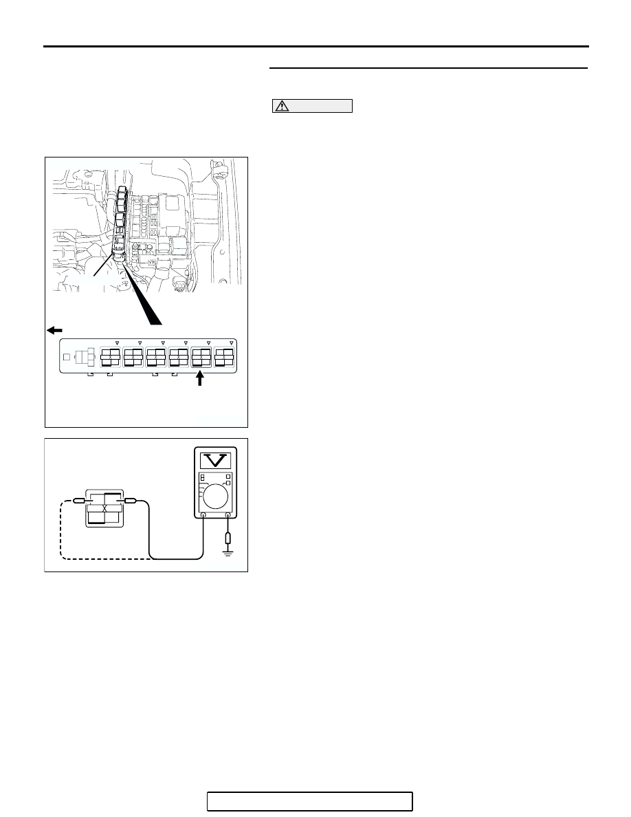
STEP 3. Measure the power supply voltage at MFI relay 
harness side connector B-17X.

CAUTION

Because it is difficult to distinguish the top and bottom of 
the MFI relay connector at the wiring harness, inspect it by 
using triangle mark on the junction block as reference.
(1) Disconnect the connector B-17X and measure at the 

harness side.

(2) Measure the voltage between terminals No. 1, No. 2 and 

ground.

• Voltage should be battery positive voltage.

Q: Is battery positive voltage (approximately 12 volts) 

present?
YES : 
Go to Step 4.
NO :  Check harness connector A-13 at intermediate 

connector for damage, and repair or replace as 
required. Refer to, GROUP 00E, Harness Connector 
Inspection 

P.00E-2

. If intermediate connector is in 

good condition, repair harness wire between relay 
box (9) and MFI relay connector B-17X (terminals No. 
1, No. 2) because of open circuit. Then confirm that 
the malfunction symptom is eliminated.

1

2

3

4

AK303017

CONNECTOR: B-17X

FRONT OF VEHICLE

B-17X

AB

HARNESS
CONNECTOR:
COMPONENT SIDE

RELAY BOX

2

1

3

4

AK303247

B-17X HARNESS 
CONNECTOR: 
COMPONENT SIDE

AB

MULTIPORT FUEL INJECTION (MFI) DIAGNOSIS

TSB Revision

MULTIPORT FUEL INJECTION (MFI) <3.8L ENGINE>

13B-1101

STEP 4. Check harness connector B-20 and B-21 at PCM 
for damage.
Q: Is the harness connector in good condition?

YES : Go to Step 5.
NO :  Repair or replace it. Refer to GROUP 00E, Harness 

Connector Inspection 

P.00E-2

. Then confirm that the 

malfunction symptom is eliminated.

AK303248

25

21

24 23 22

29 28 27 26

34 33 32 31 30

38 37 36 35

43 42 41 40 39

55

56

54 53 52 51

57

62 61 60 59 58

63

69 68 67 66 65 64

70

75 74 73 72 71

76

82 81 80 79 78 77

83

CONNECTORS: B-20, 21

PCM

AIR CLEANER

B-20

B-21 (B)

AB

B-20 HARNESS CONNECTOR: 
COMPONENT SIDE

B-21 HARNESS CONNECTOR: 
COMPONENT SIDE

MULTIPORT FUEL INJECTION (MFI) DIAGNOSIS

TSB Revision

MULTIPORT FUEL INJECTION (MFI) <3.8L ENGINE>

13B-1102

STEP 5. Measure the ignition switch-IG signal voltage at 
PCM harness side connector B-20.
(1) Disconnect the connector B-20 and measure at the harness 

side.

(2) Turn the ignition switch to the "ON" position.

(3) Measure the voltage between terminal No. 43 and ground.

• Voltage should be battery positive voltage.

(4) Turn the ignition switch to the "LOCK" (OFF) position.
Q: Is battery positive voltage (approximately 12 volts) 

present?
YES : 
Go to Step 6.
NO :  Check harness connector C-214 and C-215 at 

intermediate connector for damage, and repair or 
replace as required. Refer to, GROUP 00E, Harness 
Connector Inspection 

P.00E-2

. If intermediate 

connectors are in good condition, repair harness wire 
between ignition switch connector C-308 (terminal 
No. 2) and PCM connector B-21 (terminal No. 43) 
because of open circuit. Then confirm that the 
malfunction symptom is eliminated.

AK303092

25

21

24 23 22

29 28 27 26

34 33 32 31 30

38 37 36 35

43 42 41 40 39

CONNECTOR: B-20

B-20

PCM

AB

HARNESS CONNECTOR: 
COMPONENT SIDE

AIR CLEANER

25

21

24 23 22

29 28 27 26

34 33 32 31 30

38 37 36 35

43 42 41 40 39

AK303249

B-20 HARNESS 
CONNECTOR: 
COMPONENT SIDE

AB

MULTIPORT FUEL INJECTION (MFI) DIAGNOSIS

TSB Revision

MULTIPORT FUEL INJECTION (MFI) <3.8L ENGINE>

13B-1103

STEP 6. Measure the backup power supply voltage at PCM 
harness side connector B-20.
(1) Disconnect the connector B-20 and measure at the harness 

side.

(2) Measure the voltage between terminal No. 42 and ground.

• Voltage should be battery positive voltage.

Q: Is battery positive voltage (approximately 12 volts) 

present?
YES : 
Go to Step 7.
NO :  Repair harness wire between relay box (9) and PCM 

connector B-20 (terminal No. 42) because of short 
circuit. Then confirm that the malfunction symptom is 
eliminated.

AK303092

25

21

24 23 22

29 28 27 26

34 33 32 31 30

38 37 36 35

43 42 41 40 39

CONNECTOR: B-20

B-20

PCM

AB

HARNESS CONNECTOR: 
COMPONENT SIDE

AIR CLEANER

25

21

24 23 22

29 28 27 26

34 33 32 31 30

38 37 36 35

43 42 41 40 39

AK303187

B-20 HARNESS 
CONNECTOR: 
COMPONENT SIDE

AB


Content   ..  1198  1199  1200  1201   ..