Mitsubishi Galant 9G. Manual - part 71
SYMPTOM PROCEDURES
TSB Revision
SIMPLIFIED WIRING SYSTEM (SWS)
54B-280
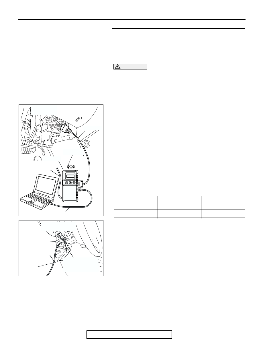
Check the input signal by using "DATA LIST" menu of the
SWS monitor.
Set each switch to the following condition to check input signals
from the variable intermittent wiper control switch:
• Ignition switch: ACC
• Windshield wiper switch: INT
CAUTION
To prevent damage to scan tool MB991958, always turn the
ignition switch to the "LOCK" (OFF) position before con-
necting or disconnecting scan tool MB991958. Connect
special tool MB991910 before connecting special tool
MB991812. Be sure to connect special tool MB991806 after
turning on special tool MB991824.
(1) Connect the special tool. Refer to "How to connect SWS
."
(2) Operate scan tool MB991958 according to the procedure
below to display "F.WIPER INT."
a. Select "Interactive Diagnosis."
b. Select "System select."
c. Select "SWS."
d. Select "SWS MONITOR."
e. Select "Function Diag."
f. Select "WIPER."
g. Select "F.WIPER INT."
(3) Check that normal conditions are displayed for the items
described in the table below.
NOTE: Also check that the windshield wiper interval
changes smoothly when the variable intermittent wiper con-
trol switch is rotated from "SLOW" to "FAST" position.
Q: Does the value change within the normal range when
the windshield intermittent wiper interval adjusting
knob is rotated?
YES : Replace the front-ECU. Check that the windshield
intermittent wiper interval changes according to the
vehicle speed or while the windshield intermittent
wiper interval adjusting knob is rotated.
NO : Refer to Inspection Procedure M-7 "ETACS-ECU
does not receive any signal from the variable
intermittent wiper control switch
ITEM NO.
ITEM NAME
NORMAL
CONDITION
ITEM 37
INT WIPER TIME
1.6
− 19.0 s
AC305411AB
MB991910
DATA LINK
CONNECTOR
MB991827
MB991824
MB991806
MB991812
AC302210
COLUMN SWITCH
CONNECTOR
COLUMN SWITCH
CONNECTOR AT
HARNESS SIDE
MB991812
AB