Mitsubishi Lancer. Manual - part 267
AC303473
18
17
15
20
12
9
13
5
2
9
3
4
1
10
6
10
12 ± 2 N·m
AC
12 ± 2 N·m
<Vehicles with A/C>
16
19
8
11
7
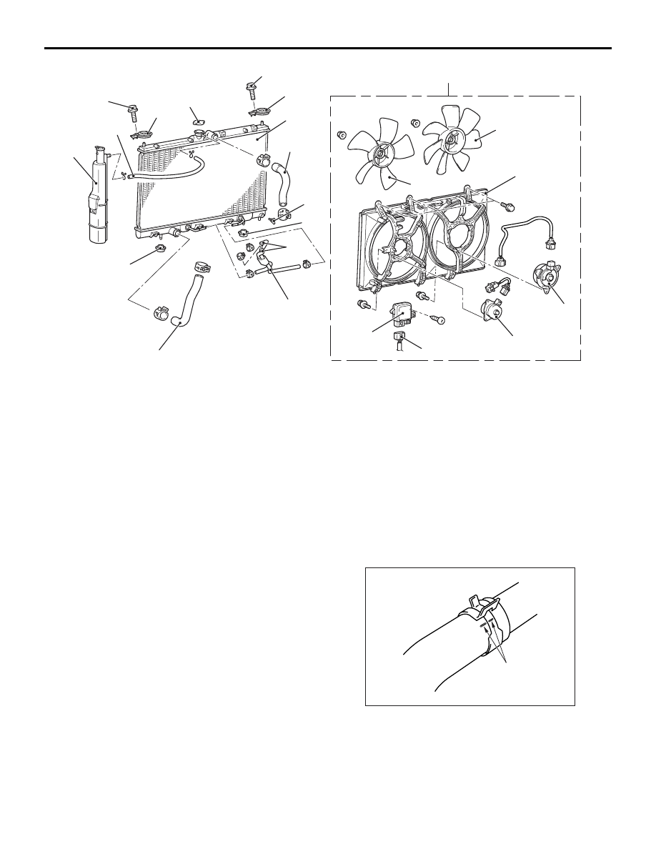
Radiator removal steps
1.
Drain plug
2.
Radiator cap
3.
Radiator condenser tank hose
4.
Radiator condenser tank assembly
<<
A
>>
>>
A
<<
5.
Radiator upper hose
<<
A
>>
>>
A
<<
6.
Radiator lower hose
7.
Cooling fan motor drive control unit
connector
8.
T/M oil cooler line hose connection
<A/T>
9.
Radiator support upper insulator
•
Radiator and cooling fan motor &
shroud assembly
10. Radiator support lower insulator
11. T/M oil cooler line hose <A/T>
12. Cooling fan motor & shroud
assembly
13. Radiator assembly
Cooling fan motor removal
steps
3.
Radiator condenser tank hose
<<
A
>>
>>
A
<<
5.
Radiator upper hose
7.
Cooling fan motor drive control unit
connector
12. Cooling fan motor & shroud
assembly
15. Cooling fan (L.H.)
16. Cooling fan (R.H.) <Vehicles with
A/C>
17. Cooling fan motor drive control unit
18. Cooling fan motor (L.H.)
19. Cooling fan motor (R.H.) <Vehicles
with A/C>
20. Cooling fan shroud
RADIATOR
ENGINE COOLING
14-34
REMOVAL SERVICE POINT
<<A>> RADIATOR UPPER HOSE/RADIA-
TOR LOWER HOSE DISCONNECTION
AC200641AC
Mating marks
Make mating marks on the radiator hose and the
hose clamp. Disconnect the radiator hoses.
Cooling fan motor removal steps
(Continued)