Mitsubishi Lancer. Manual - part 260


  Index      Mitsubishi     Mitsubishi Lancer - service repair manual 2006 year


Search            


Content   ..  258  259  260  261   ..


Mitsubishi Lancer. Manual - part 260


TROUBLESHOOTING

ENGINE COOLING

14-6

INSPECTION PROCEDURE FOR 
TROUBLE SYMPTOMS

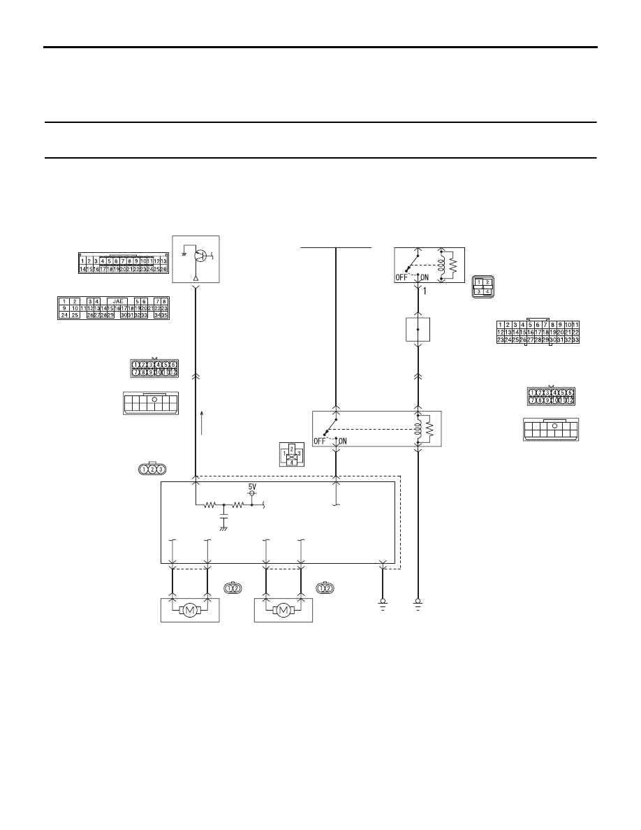
INSPECTION PROCEDURE 1: Cooling Fan (L.H.) and Cooling Fan (R.H.) <4G1 (Vehicles with A/C)> or 
A/C Condenser Fan <4G6> do not Operate

Wire colour code
B : Black     LG : Light green
G : Green     L : Blue      
W : White     Y : Yellow
SB : Sky blue     BR : Brown 
O : Orange     GR : Gray  
R : Red     P : Pink     V : Violet 

FAN CONTROL 
RELAY
              A-09X

ENGINE CONTROL 
RELAY
B-16X

AC303577

A-18-1

COOLING FAN
MOTOR (L.H.)

COOLING FAN
MOTOR (R.H.)
<4G1 (VEHICLES
WITH A/C>
OR
A/C CONDENSER
FAN MOTOR <4G6>

A-18-2

A-18

COOLING FAN
MOTOR DRIVE
CONTROL UNIT

1    A-13 <LHD>
12  C-111 <RHD>

ENGINE-ECU <M/T> OR
ENGINE-A/T-ECU <A/T>

21  C-123 <M/T>
18  C-122 <A/T>

6

1

5

12

11

7

9

8

10

2 3

4

(MU802322)

(MU801824)

C-123

(MU803784)

C-122

(MU802611)

A-13

C-111

L

L

2

2

2

1

1

1

B

L

2

3

4

B-W

FUSIBLE
LINK No.2

B

3

1

R-Y

R-Y

8    A-13 <LHD>
11  C-111 <RHD>

6

1

5

12

11

7

9

8

10

2 3

4

(MU802611)

J/C (6)

C-12 <LHD>
C-134 <RHD>

R-Y

33

28

A-13

C-111

Cooling Fan (L.H.) and Cooling Fan (R.H.) or A/C Condenser Fan Drive Circut

AB

CIRCUIT OPERATION

• The cooling fan motor drive control unit is pow-

ered from fusible link (2).

• The engine-ECU <M/T> or engine-A/T-ECU 

<A/T> uses input signals from the A/C switch, the 
water temperature sensor unit and the vehicle 
speed sensor <M/T> or the output shaft speed 
sensor <A/T> to control the speed of the cooling 
fan motor (L.H.) and the cooling fan motor (R.H.) 
<4G1 (Vehicles with A/C)> or A/C condenser fan 
motor <4G6>.

TROUBLESHOOTING

ENGINE COOLING

14-7

• The engine-ECU <M/T> or engine-A/T-ECU 

<A/T> controls the cooling fan motor drive control 
unit to activate the cooling fan motor (L.H.) and 
the cooling fan motor (R.H.) <4G1 (Vehicles with 
A/C)> or A/C condenser fan motor <4G6>.

TECHNICAL DESCRIPTION

• The cause could be a malfunction of the cooling 

fan motor drive control unit power supply or earth 
circuit.

• If the communication line wiring harness between 

the cooling fan motor drive control unit and the 
engine-ECU <M/T> or engine-A/T-ECU <A/T> is 
short-circuited to earth, the cooling fan motor 
(L.H.) and the cooling fan motor (R.H.) <4G1 
(Vehicles with A/C)> or the A/C condenser fan 
motor <4G6> will not rotate.

• The cause could also be a malfunction of the 

cooling fan motor (L.H.). <Vehicles without A/C>

• The cause could also be a malfunction of imput 

signal from the A/C switch, the water temperature 
sensor unit and the vehicle speed sensor <M/T> 
or the output shaft speed sensor <A/T> to the 
engine-ECU <M/T> or engine-A/T-ECU <A/T>.

• The cause could also be a malfunction of the 

cooling fan motor drive control unit or the 
engine-ECU <M/T> or engine-A/T-ECU <A/T>.

TROUBLESHOOTING HINTS

• Malfunction of fusible link (2)

• Malfunction of fan control relay

• Malfunction of cooling fan motor (L.H.) <Vehicles 

without A/C>

• Malfunction of cooling fan motor drive control unit

• Malfunction of engine-ECU <M/T> or 

engine-A/T-ECU <A/T>

• Damaged wiring harness or connector

DIAGNOSIS

STEP 1. Check the cooling fan motor (L.H.). 
<Vehicles without A/C>
Refer to 

P.14-24

.

Q: Is the cooling fan motor (L.H.) in good condition?

YES : 

Go to Step 2 .

NO : 

Replace the cooling fan motor (L.H.) (Refer 
to 

P.14-33

) <4G1> (Refer to 

P.14-35

<4G6>. Then go to Step 24 .

STEP 2. Measure the power supply voltage at 
cooling fan motor drive control unit connector 
A-18.

AC100293

A-18

3

2

1

Connector: A-18

AD

(1) Disconnect cooling fan motor drive control unit 

connector A-18 and measure wiring harness side 
connector.

(2) Turn the ignition switch to the "ON" position.

AC000246AF

A-18 Connector
(Component side)

(3) Measure the voltage between cooling fan motor 

drive control unit connector A-18 terminal 3 and 
body earth.

• The voltage should measure system voltage.

(4) Turn the ignition switch to the "LOCK" (OFF) 

position.

(5) Connect cooling fan motor drive control unit 

connector A-18.

Q: Is the measured voltage system voltage?

YES : 

Go to Step 17 .

NO : 

Go to Step 3 .

TROUBLESHOOTING

ENGINE COOLING

14-8

STEP 3. Check the cooling fan motor drive 
control unit connector A-18.

AC100293

A-18

3

2

1

Connector: A-18

AD

Q: Is the connector in good condition?

YES : 

Go to Step 4 .

NO : 

Repair or replace the connector. Then go to 
Step 24 .

STEP 4. Check the fusible link No.2.

AC303509

AB

Fusible link
No.2

Relay box

Q: Is the fusible link No.2 in good condition?

YES : 

Go to Step 5 .

NO : 

Replace the fusible link No.2. Then go to 
Step 24 .

STEP 5. Measure the power supply voltage at fan 
control relay connector A-09X.

AC303510

AB

Fan control relay

Relay box

Connector: A-09X

A-09X

(1) Disconnect fan control relay connector A-09X 

(remove the fan control relay) and measure relay 
box side connector.

(2) Turn the ignition switch to the "ON" position.

AC303511AB

A-09X Connector
(Relay box side)

(3) Measure the voltage between fan control relay 

connector A-09X terminal 4 and body earth.

• The voltage should measure system voltage.

(4) Turn the ignition switch to the "LOCK" (OFF) 

position.

(5) Connect fan control relay connector A-09X 

(install the fan control relay).

Q: Is the measured voltage system voltage?

YES : 

Go to Step 8 .

NO : 

Go to Step 6 .

STEP 6. Check the fan control relay connector 
A-09X.

AC303510

AB

Fan control relay

Relay box

Connector: A-09X

A-09X

Q: Is the connector in good condition?

YES : 

Go to Step 7 .

NO : 

Repair the connector or replace the relay 
box. Then go to Step 24 .

TROUBLESHOOTING

ENGINE COOLING

14-9

STEP 7. Check the harness wire between fusible 
link No.2 and fan control relay connector A-09X 
terminal 4.

AC303509

AB

Fusible link
No.2

Relay box

AC303510

AB

Fan control relay

Relay box

Connector: A-09X

A-09X

Q: Is the harness wire in good condition?

YES : 

An intermittent malfunction is suspected 

(Refer to GROUP 00 - How to use 
troubleshooting 

P.00-5

).

NO : 

Repair the damaged harness wire. Then go 
to Step 24 .

STEP 8. Check the fan control relay.
Refer to 

P.14-23

.

Q: Is the fan control relay in good condition?

YES : 

Go to Step 9 .

NO : 

Replace the fan control relay. Then go to 
Step 24 .

STEP 9. Check the fan control relay connector 
A-09X.

AC303510

AB

Fan control relay

Relay box

Connector: A-09X

A-09X

Q: Is the connector in good condition?

YES : 

Go to Step 10 .

NO : 

Repair the connector or replace the relay 
box. Then go to Step 24 .

STEP 10. Check the harness wire between fan 
control relay connector A-09X terminal 2 and 
cooling fan motor drive control unit connector 
A-18 terminal 3.

AC303510

AB

Fan control relay

Relay box

Connector: A-09X

A-09X

AC100293

A-18

3

2

1

Connector: A-18

AD

Q: Is the harness wire in good condition?

YES : 

Go to Step 11 .

NO : 

Repair the damaged harness wire. Then go 
to Step 24 .


Content   ..  258  259  260  261   ..