Mitsubishi Lancer. Manual - part 256


  Index      Mitsubishi     Mitsubishi Lancer - service repair manual 2006 year


Search            


Content   ..  254  255  256  257   ..


Mitsubishi Lancer. Manual - part 256


CONTROL LINK, UPPER ARM AND LOWER ARM

REAR SUSPENSION

34-10

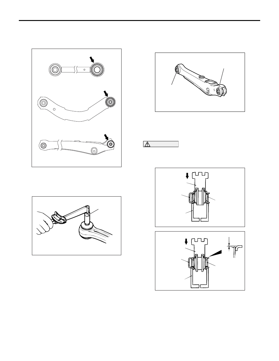
CONTROL LINK <Intense>/UPPER ARM 
<Intense>/LOWER ARM PILLOW BALL 
BUSHING STARTING TORQUE CHECK

AC107127AG

Lower arm pillow ball bushing

Upper arm pillow ball bushing <Intense>

Control link pillow ball bushing <Intense>

Check each pillow ball bushing as follows.
1. Insert the mounting bolt to the pillow ball bushing. 

In the opposite direction, insert a washer, then 
install the mounting nut.

AC102498 AC

MB990326

2. After rotating the inner sleeve (contained washer) 

several times, measure the starting torque of the 
pillow ball bushing using special tool preload 
socket (MB990326).

Standard value: 0.5 

 3.0 N⋅ m

3. If the measured value exceeds the standard 

value, replace the control link, the upper arm, or 
the lower arm pillow ball bushing.

4. If the measured value is lower than the standard 

value, check that the pillow ball bushing turns 
smoothly without excessive play. If there is no 
excessive play and it turns smoothly, the pillow 
ball bushing can be reused.

LOWER ARM BUSHING AND LOWER 
ARM PILLOW BALL BUSHING 
REPLACEMENT

M1341011800204

AC304399 AB

Lower arm bushing

Lower arm pillow 
ball bushing

Lower arm bushing

Replace the lower arm bushing and lower arm pillow 
ball bushing as follows.

LOWER ARM BUSHING REPLACEMENT

CAUTION

Because the outside diameter of both edges of 
the bushing are different, be careful not to mis-
take the direction.

AC006168 AC

Driving Out

MB991447

Lower arm

MB991448

MB991449

AC006169 AC

1.5 mm

Press-Fitting

MB991447

Lower arm

MB991448

MB991449

Use following special tools to drive out and press fit 
the bushing.

• Bushing remover and installer (MB991447)

• Bushing remover and installer base (MB991448)

• Bushing remover and installer supporter 

(MB991449)

After press fitting, the space between the edges of 
the bushing outer sleeve and of the lower arm should 
be 1.5 mm.

CONTROL LINK, UPPER ARM AND LOWER ARM

REAR SUSPENSION

34-11

LOWER ARM PILLOW BALL BUSHING 
REPLACEMENT

AC102522 AC

3 mm

MB990996

Lower arm

MB990971

MB990969

Use following special tools to drive out and press fit 
the bushing.

• Lower arm bushing remover and installer 

(MB990957)

• Guide (MB990969)

• Base (MB990971)

• Lower arm bushing arbor (MB990996)

After press fitting, the space between the edges of 
the bushing outer sleeve and of the lower arm should 
be 3 mm.

TRAILING ARM ASSEMBLY

REAR SUSPENSION

34-12

TRAILING ARM ASSEMBLY

REMOVAL AND INSTALLATION

M1341002200594

CAUTION


*

: Indicates parts which should be temporarily tightened, and then fully tightened with the vehicle on 

the earth in the unladen condition.

Pre-removal Operation
• Brake Fluid Draining

• Rear Hub Assembly Removal (Refer to GROUP 27, Rear 

Axle Hub Assembly 

P.27-5

).

Post-installation Operation
• Rear Hub Assembly Installation (Refer to GROUP 27, 

Rear Axle Hub Assembly 

P.27-5

).

• Brake Fluid Supplying and Bleeding (Refer to GROUP 

35A, On-vehicle Service 

− Bleedin

P.35A-6

).

• Rear Wheel Alignment Check and Adjustment (Refer to 

P.34-6

).

• Parking Brake Lever Stroke Adjustment (Refer to GROUP 

36, On-vehicle Service 

− Parking Brake Lever Stroke 

Check and Adjustment 

P.36-3

).

AC101449
AC301223

AC304155 AB

90 ± 10 N·m*

120 ± 10 N·m*

95 ± 15 N·m*

63 ± 7 N·m

6

7

8

1

10

11

2

3

4

120 ± 10 N·m*

15 ± 2 N·m

N

9

5

Removal steps 

<<

A

>>

Lifting point

1.

Rear ABS Sensor (Refer to 
GROUP 35B, ABS Sensor 

P.35B-68

).

2.

Parking brake cable

3.

Brake hose and trailing arm 
connection

4.

Rear parking brake assembly

>>

A

<<

5.

Lower arm assembly and stabilizer 
link connection

6.

Lower arm assembly and shock 
absorber connection

7.

Control link and trailing arm 
connection

8.

Upper arm assembly and trailing 
arm connection

Removal steps (Continued)

TRAILING ARM ASSEMBLY

REAR SUSPENSION

34-13

REMOVAL SERVICE POINTS
<<A>> LIFTING POINT

AC006171 AC

Trailing arm

When removing the trailing arm, move the lifting arm 
slightly towards the front of the vehicle so that it will 
not be in the way.

<<B>> LOWER ARM ASSEMBLY AND 
TRAILING ARM DISCONNECTION

AC107126 AB

Piece of wood

After supporting the lower arm assembly with a jack, 
separate the lower arm assembly and trailing arm 
connection.

INSTALLATION SERVICE POINT
>>A<< STABILIZER LINK INSTALLATION

AC103744

A

AC

Tighten the self-locking nut until the stabilizer link 
thread part protruding length meets the standard 
value.

Standard value (A): 6 

 8 mm

INSPECTION

M1341002300182

• Check the bushings for wear and deterioration.

• Check the trailing arm for bending or damage.

TRAILING ARM BUSHING 
REPLACEMENT

M1341011300221

AC006172 AE

Driving out

MB990890

Trailing arm

MB990947

MB991816

1. Use the following special tools to drive out the 

trailing arm bushing.

• Rear suspension bushing base (MB990890)

• Lower arm bushing arbor (MB990947)

AC006173 AB

Bushing remover and installer base (MB991816)

2. Set the installation direction and installation 

location of the trailing arm bushing.
(1) Place the long projection end of the trailing 

arm bushing inner pipe towards the inside of 
the vehicle.

(2) Make sure that the hollow of the trailing arm 

bushing is located as shown in the illustration.

<<

B

>>

9.

Lower arm assembly and trailing 
arm connection

10. Trailing arm and body connection
11. Trailing arm

Removal steps (Continued)


Content   ..  254  255  256  257   ..