Mitsubishi Lancer. Manual - part 252


  Index      Mitsubishi     Mitsubishi Lancer - service repair manual 2006 year


Search            


Content   ..  250  251  252  253   ..


Mitsubishi Lancer. Manual - part 252


STRUT ASSEMBLY

FRONT SUSPENSION

33-10

>>B<< STRUT NUT (SELF-LOCKING NUT) 
INSTALLATION

1. Ensure that the bearing is seated correctly.
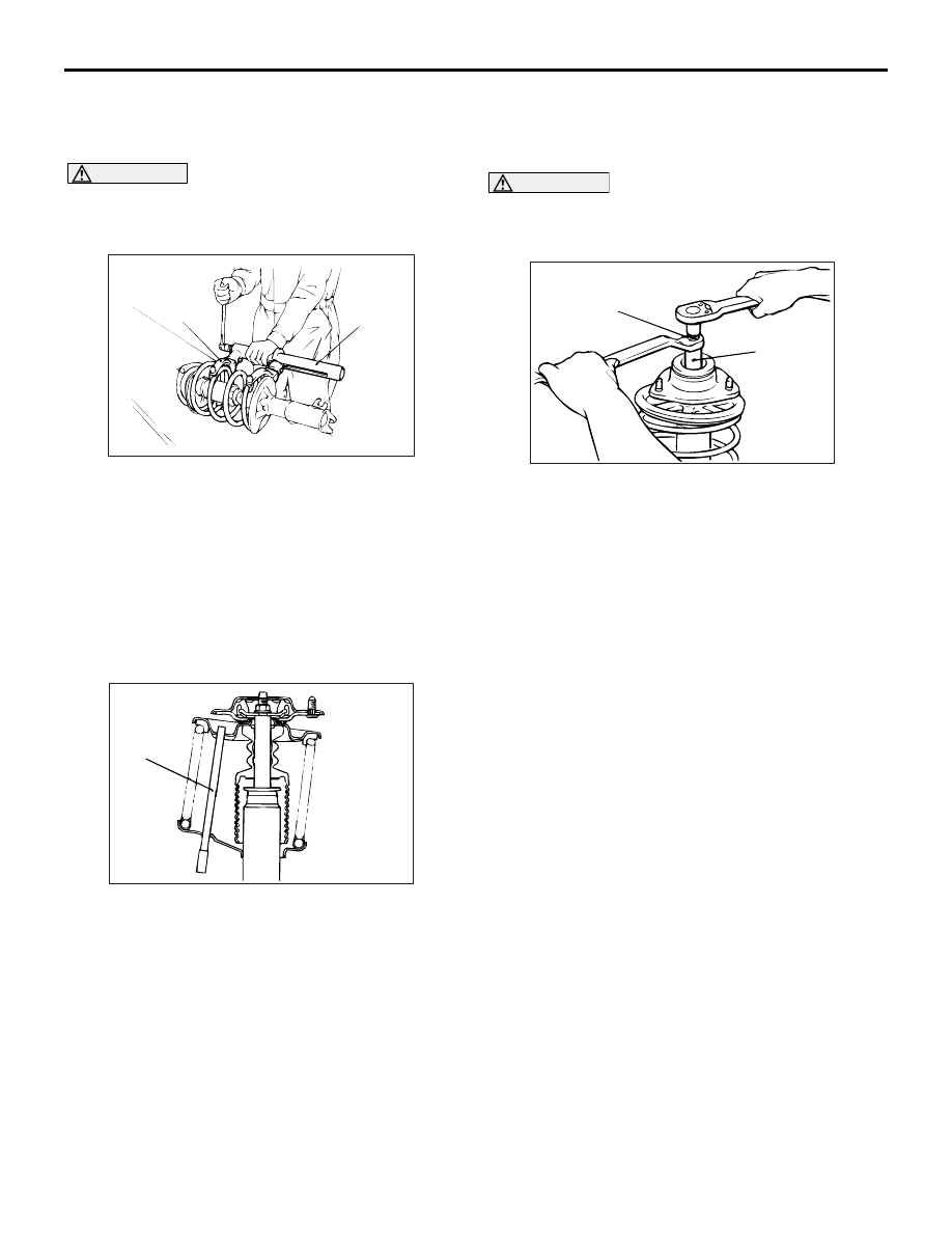
CAUTION

Do not use an impact wrench to tighten the bolt 
of special tool spring compressor body 
(MB991237), otherwise the special tool will break.

AC001085 AB

MB991238

MB991237

2. Install following special tools to the strut assembly 

same as its removal.

• Spring compressor body (MB991237)

• Arm set (MB991238)

3. While the coil spring is being compressed by the 

special tools, temporarily tighten the strut nut 
(self-locking nut).

4. Align the hole in the strut spring lower seat with 

the hole in the spring upper seat.
NOTE: 

AC006091 AB

Rod

Using a rod as shown facilitates the alignment.

5. Align lower end of the coil spring with the groove 

in the spring lower seat, and then loosen the 
special tools.

CAUTION

Do not use an impact wrench to tighten the 
self-locking nut, otherwise the strut nut 
(self-locking nut) will be damaged.

AC006091 AB

MB991681

MB991682

6. Using following special tools, tighten the strut nut 

(self-locking nut) to 60 

± 10 N⋅ m.

• Wrench (MB991681)

• Socket (MB991682)

INSPECTION

M1332001400188

• Check the strut bearing for wear or rust.

• Check the rubber parts for damage or deteriora-

tion.

• Check the coil spring for deformation, deteriora-

tion or damage.

• Check the strut for deformation.

LOWER ARM

FRONT SUSPENSION

33-11

LOWER ARM

REMOVAL AND INSTALLATION

M1332001600331

CAUTION

*

: Indicates parts which should be temporarily tightened, and then fully tightened with the vehicle on 

the earth in an unladen condition.

Post-installation Operation
• Check the lower arm ball joint cover for cracks or damage 

by pushing it with your finger.

• Front Wheel Alignment Check and Adjustment (Refer to 

P.33-6

).

AC006097 AD

7

1

3

4

5

108 ± 10 N·m

186 ± 10 N·m*

7

3

6

N

Specified grease :
     Multipurpose grease SAE J310, 
     NLGI No.2 or equivalent

167 ± 9 N·m

6

2

Removal steps 

>>

A

<< 1.

Self-locking nut

2.

Bolt

3.

Stabilizer rubber

4.

Collar

5.

Lower arm bolt

<<

A

>>

6.

Lower arm bolt

7.

Lower arm assembly

REMOVAL SERVICE POINT
<<A>> LOWER ARM BOLT REMOVAL

AC006133 AD

Lower arm bolt (front)

Transmission jack

Piece of wood

LOWER ARM

FRONT SUSPENSION

33-12

As for the L.H. lower arm assembly, withdraw the 
lower arm bolt (front) with the transmission lift up by 
using a transmission jack.

INSTALLATION SERVICE POINT
>>A<< SELF-LOCKING NUT INSTALLA-
TION

AC101741AC

A

Tighten the self-locking nut until the stabilizer link 
thread part protruding length meets the standard 
value.

Standard value (A): 22 

± 1.5 mm

INSPECTION

M1332001700286

• Check the lower arm bushings for wear and dete-

rioration.

• Check the lower arm assembly for bend or break-

age.

• Check all bolts for condition and straightness.

LOWER ARM BALL JOINT STARTING 
TORQUE CHECK

AC404846AF

MB991006

1. After shaking the ball joint stud several times, use 

special tool preload socket (MB991006) to 
measure the starting torque of the ball joint.

Standard value: 0 

 3.9 N⋅ m

2. If the measured value is not within the standard 

value, or if the ball joint is difficult to turn or does 
not turn smoothly, replace the lower arm 
assembly.

LOWER ARM BALL JOINT COVER 
CHECK

1. Check the lower arm ball joint cover for cracks or 

damage by pushing it with your finger.

2. If the lower arm ball joint cover is cracked or 

damaged, replace the lower arm assembly.
NOTE: Cracks or damage to the dust cover may 
cause damage to the ball joint. When it is dam-
aged during service work, replace the lower arm 
ball joint cover.

LOWER ARM BALL JOINT COVER 
REPLACEMENT

M1332008200260

If the lower arm ball joint cover is damaged acciden-
tally during service work, replace the lower arm ball 
joint cover as follows:
1. Remove the lower arm ball joint cover.
2. Apply specified grease to the lip and the inside of 

a new lower arm ball joint cover.

Specified grease: Multipurpose grease SAE 
J310, NLGI No.2 or equivalent
Grease amount for the inside the dust cover 
(reference): 8 

 10 g

AC006135 AD

MB990800

Lower arm 
ball joint 
cover

3. Using special tool ball joint remover and installer 

(MB990800), drive in the lower arm ball joint 
cover until it is fully seated.

AC107030

AC

22 mm

Lower arm 
ball joint cover

LOWER ARM

FRONT SUSPENSION

33-13

4. Position the lower arm ball joint cover as shown in 

the illustration. Make sure that there is no 
abnormal bulge or pressure applied on the lower 
arm ball joint cover.

5. Check the lower arm ball joint cover for cracks or 

damage by pushing it with your finger.

LOWER ARM BUSHING (REAR) 
REPLACEMENT

M1332008100348

AC006136 AD

Lower arm bushing (rear)

Replace the lower arm bushing (rear) as follows:

AC006137 AC

MB990883

MB990972

MB990887

MB990890

Lower arm
assembly

1. Use following special tools to drive out the lower 

arm bushing (rear). 

• Rear suspension bushing arbor (MB990883)

• Torsion bar bushing remover base (MB990972)

• Ring (MB990887)

AC006138 AC

MB990883

MB990972

MB990887

MB990890

Lower arm
assembly

Projection

30˚

Lower arm assembly

Outer tube

Rear suspension bushing base (MB990890)

2. Position the lower arm bushing (rear) so that its 

projection is as shown, and then use the special 
tools to press in the bushing.

3. Press the lower arm bushing (rear) until its outer 

tube is flush with the lower arm assembly surface.


Content   ..  250  251  252  253   ..