Mitsubishi Lancer. Manual - part 221
FENDER
BODY
42-6
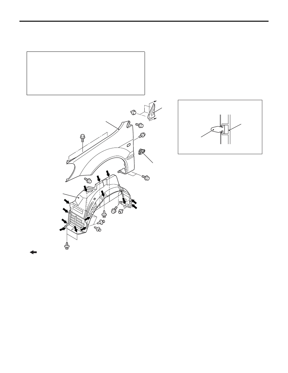
FENDER
REMOVAL AND INSTALLATION
M1421001900302
Pre-removal and Post-installation Operation
• Front Bumper Removal and Installation (Refer to GROUP
51, Front Bumper
• Front Deck Garnish Removal and Installation (Refer to
GROUP 51, Windshield Wiper and Washer
• Side Air Dam Removal and Installation <Vehicles with
side air dam> (Refer to GROUP 51, Side Air Dam
AC300491
AC304753
AC303863
Clip
Section A – A
AB
A
A
1
2
3
3
4
Note
: Clip positions
Removal steps
1. Splash shield
<<
A
>> >>
A
<< 2. Side turn-signal lamp
3. Delta outer garnish
4. Fender
Removal steps (Continued)