Mitsubishi Lancer. Manual - part 205
CHARGING SYSTEM
ENGINE ELECTRICAL
16-12
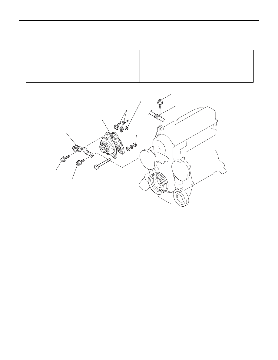
ALTERNATOR ASSEMBLY
REMOVAL AND INSTALLATION <4G1>
M1161001400548
Pre-removal Operation
• Under Cover Removal
• Drive Belt Removal (Refer to GROUP 11A - Crankshaft
Pulley
).
Post-installation Operation
• Drive Belt Installation (Refer to GROUP 11A - Crankshaft
Pulley
).
• Drive Belt Tension Adjustment (Refer to GROUP 11A -
).
• Under Cover Installation
AC303729
1
2
4
3
44 ± 10 N·m
23 ± 2 N·m
24 ± 3 N·m
12 ± 2 N·m
AB
13 ± 3 N·m
Removal steps
1.
Power steering pressure hose
clamp
2.
Alternator connector and terminal
3.
Alternator adjusting brace
<<
A
>>
4.
Alternator assembly
REMOVAL SERVICE POINT
<<A>> ALTERNATOR ASSEMBLY
REMOVAL
Remove the alternator assembly from above the
vehicle.