Mitsubishi Lancer (4A9 engine). Manual - part 148
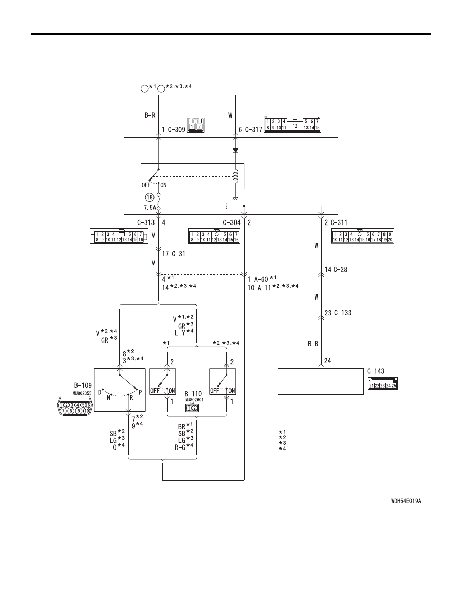
REAR VIEW CAMERA
CHASSIS ELECTRICAL
54A-254
Rear View Camera Circuit
ETACS-ECU
BACK-UP
LAMP
SWITCH
<M/T>
<A/T, CVT>
INHIBITOR
SWITCH
Wire colour code
B : Black LG : Light green G : Green L : Blue W : White Y : Yellow SB : Sky blue
BR : Brown O : Orange GR : Grey R : Red P : Pink V : Violet PU : Purple SI : Silver
IGNITION
SWITCH (IG1)
IG1
RELAY
FUSIBLE
LINK
44
34
1800-DIESEL
:
1600
:
1800-PETROL-DOHC, 2000
:
NOTE
1800-PETROL-SOHC
:
MULTIVISION
DISPLAY