Mitsubishi Lancer (4A9 engine). Manual - part 57


  Index      Mitsubishi     Mitsubishi Lancer (4A9 engine) 12GS41 & 44S - service repair manual


Search            


Content   ..  55  56  57  58   ..


Mitsubishi Lancer (4A9 engine). Manual - part 57


TROUBLESHOOTING

ACTIVE STABILITY CONTROL SYSTEM (ASC)

35C-81

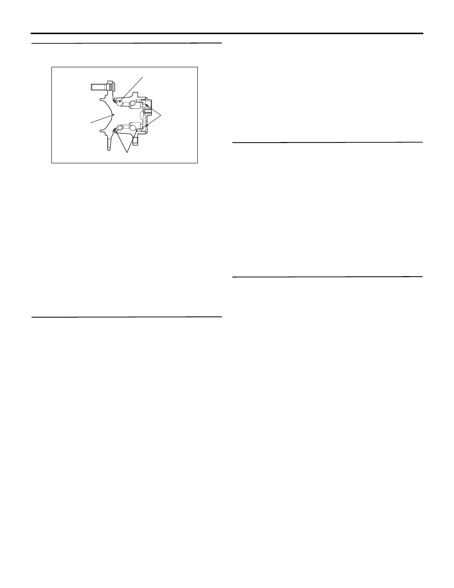
STEP 10. Check of wheel speed detection 
encoder

AC700162

Rear hub

Oil seal

Ball bearing

Magnetic
encoder

AB

Check the encoder for adhesion of foreign materials 
or deformation.

Q: Is the check result normal?

YES : 

Go to Step 11.

NO (Adhesion of foreign materials) : 

Remove the 

foreign materials and clean the encoder so 
as not to disturb the magnetization pattern 
on it while taking care of the magnet, 
magnetic substance, and magnetic 
attraction. Then go to Step 13.

NO <Deformation> : 

Replace the rear wheel hub 

assembly <RR> (Refer to GROUP 27 

− 

Rear axle hub assembly ). Then go to Step 
13.

STEP 11. Check whether the diagnosis code is 
reset.
(1) Erase the diagnosis code.
(2) Drive the vehicle at 20 km/h or higher.

NOTE: The ABS warning lamp does not turn OFF 
in some cases unless the vehicle runs at 20 km/h 
or higher.

Q: Is the diagnosis code No.C1049 set?

YES : 

Replace the wheel speed sensor <RR> 

(Refer to 

P.35C-188

). Then go to Step 12.

NO : 

Intermittent malfunction (Refer to GROUP 
00 

− How to Use Troubleshooting/How to 

Cope with Intermittent Malfunctions).

STEP 12. Check whether the diagnosis code is 
reset.
(1) Erase the diagnosis code.
(2) Drive the vehicle at 20 km/h or higher.

NOTE: The ABS warning lamp does not turn OFF 
in some cases unless the vehicle runs at 20 km/h 
or higher.

Q: Is the diagnosis code No.C1049 set?

YES : 

Replace the hydraulic unit (integrated with 

ASC-ECU) (Refer to 

P.35C-185

). Then go 

to Step 13.

NO : 

This diagnosis is complete.

STEP 13. Check whether the diagnosis code is 
reset.
(1) Erase the diagnosis code.
(2) Drive the vehicle at 20 km/h or higher.

NOTE: The ABS warning lamp does not turn OFF 
in some cases unless the vehicle runs at 20 km/h 
or higher.

Q: Is the diagnosis code No.C1049 set?

YES : 

Return to Step 1.

NO : 

This diagnosis is complete.

TROUBLESHOOTING

ACTIVE STABILITY CONTROL SYSTEM (ASC)

35C-82

Code No. C104B Abnormality in FL wheel inlet valve system


Code No. C104F Abnormality in FR wheel inlet valve system


Code No. C1053 Abnormality in RL wheel inlet valve system


Code No. C1057 Abnormality in RR wheel inlet valve system


Code No. C105F Abnormality in FL wheel outlet valve system


Code No. C1063 Abnormality in FR wheel outlet valve system


Code No. C1067 Abnormality in RL wheel outlet valve system


Code No. C105B Abnormality in RR wheel outlet valve system


Code No. C1200 Abnormality in FL/RR wheel cut valve system


Code No. C1204 Abnormality in FR/RL wheel cut valve system


Code No. C1208 Abnormality in FL/RR wheel suction valve system


Code No. C120C Abnormality in FR/RL wheel suction valve system

CAUTION

• If there is any problem in the CAN bus lines, 

an incorrect diagnosis code may be set. Prior 
to this diagnosis, diagnose the CAN bus lines 
(Refer to GROUP 54C 

 CAN Bus Diagnostics 

Table ).

• Whenever ECU is replaced, ensure that the 

CAN bus lines are normal.

• When the hydraulic unit (integrated with ASC-

ECU) is replaced, always carry out the calibra-
tion of the steering wheel sensor, the G and 
yaw rate sensor and brake fluid pressure sen-
sor (Refer to 

P.35C-182

P.35C-183

 an

P.35C-

184

).

OPERATION

• ASC-ECU contains the power supply circuit (ter-

minal No. 32) for the solenoid valve. The solenoid 
valve is energised by the valve relay, which is 
incorporated in ASC-ECU.

• The valve relay, which is incorporated in ASC-

ECU, is always energising the solenoid valve 
unless the initial check is in progress when the 
ignition switch is turned on, or the recurrent sys-
tem check is in progress.

• ASC-ECU activates the solenoid valve by turning 

on its driving transistor.

DIAGNOSIS CODE SET CONDITIONS
These diagnosis codes will be set under the cases 
below:

• The solenoid valve is not energized even after 

ASC-ECU has turned on the driving transistor 
(Open circuit is present in the power supply cir-
cuit to the ASC-ECU solenoid valve, or the valve 
relay has failed).

• After ASC-ECU has turned off the driving transis-

tor, the solenoid valve still remains energized 
(short in the solenoid valve circuit).

• When a solenoid valve failure is detected

PROBABLE CAUSES

• ASC-ECU malfunction

DIAGNOSIS PROCEDURE

STEP 1. M.U.T.-III CAN bus diagnosis
Use M.U.T.-III to diagnose the CAN bus lines.

Q: Is the check result normal?

YES : 

Go to Step 3.

NO : 

Repair the CAN bus lines (Refer to GROUP 
54C 

− CAN Bus Diagnostics Table ). On 

completion, go to Step 2.

STEP 2. Diagnosis code recheck after resetting 
CAN bus lines

Q: Is the relevant diagnosis code set?

YES : 

Go to Step 3.

NO : 

This diagnosis is complete.

STEP 3. Check whether the diagnosis code is 
reset.
Erase the diagnosis code.

Q: Is the relevant diagnosis code set?

YES : 

Replace the hydraulic unit (integrated with 

ASC-ECU) (Refer to 

P.35C-185

). Then go 

to Step 4.

NO : 

Intermittent malfunction (Refer to GROUP 
00 

− How to Use Troubleshooting/How to 

Cope with Intermittent Malfunctions ).

STEP 4. Check whether the diagnosis code is 
reset.
Erase the diagnosis code.

Q: Is the relevant diagnosis code set?

YES : 

Return to Step 1.

NO : 

This diagnosis is complete.

TROUBLESHOOTING

ACTIVE STABILITY CONTROL SYSTEM (ASC)

35C-83

Code No. C2104 Faulty valve power supply circuit

Solenoid Valve and Motor Power Source Circuit

MOTOR 
POWER 
SOURCE

SOLENOID 
VALVE 
POWER 
SOURCE

ASC-ECU

SOLENOID 
VALVE 
POWER 
SOURCE

MOTOR POWER 
SOURCE

Wire colour code 
B : Black     LG : Light green     G : Green     L : Blue     W : White     Y : Yellow     SB : Sky blue 
BR : Brown     O : Orange     GR : Grey     R : Red     P : Pink     V : Violet     PU : Purple     SI : Silver

SOLENOID VALVE

HYDRAULIC UNIT

MOTOR

FUSIBLE
LINK

27

FUSIBLE
LINK

26

ACB02566

AC612691

AO

Connector: A-58 <LHD>

A-58 (B)

AC701238 AF

Connector: A-58 <RHD>

A-58 (B)

TROUBLESHOOTING

ACTIVE STABILITY CONTROL SYSTEM (ASC)

35C-84

CAUTION

• If there is any problem in the CAN bus lines, 

an incorrect diagnosis code may be set. Prior 
to this diagnosis, diagnose the CAN bus lines 
(Refer to GROUP 54C 

 CAN Bus Diagnostics 

Table ).

• Whenever ECU is replaced, ensure that the 

CAN bus lines are normal.

• When the hydraulic unit (integrated with ASC-

ECU) is replaced, always carry out the calibra-
tion of the steering wheel sensor, the G and 
yaw rate sensor and brake fluid pressure sen-
sor (Refer to 

P.35C-182

P.35C-183

 an

P.35C-

184

).

OPERATION

• ASC-ECU contains the power supply circuit (ter-

minal No.32) for the solenoid valve. The solenoid 
valve is energised by the valve relay, which is 
incorporated in ASC-ECU.

• The valve relay, which is incorporated in ASC-

ECU, is always energising the solenoid valve 
unless the initial check is in progress when the 
ignition switch is turned on, or the recurrent sys-
tem check is in progress.

DIAGNOSIS CODE SET CONDITIONS
This diagnosis code will be set when the solenoid 
valve supply voltage is not within the standard value.

PROBABLE CAUSES

Current trouble

• Fusible link malfunction

• Damaged wiring harness and connectors

• Abnormality in battery or alternator

• ASC-ECU malfunction

Past trouble

• Carry out diagnosis with particular emphasis on 

wiring harness and connector failures between 
the power supply circuit (terminal No.32) to ASC-
ECU solenoid valve or earth circuit (terminal 
No.16 and 47). For diagnosis procedures, refer to 
How to treat past trouble (GROUP 00 

− How to 

Use Troubleshooting/How to Treat Past Trouble ).

DIAGNOSIS PROCEDURE

STEP 1. M.U.T.-III CAN bus diagnosis
Use M.U.T.-III to diagnose the CAN bus lines.

Q: Is the check result normal?

YES : 

Go to Step 3.

NO : 

Repair the CAN bus lines (Refer to GROUP 
54C 

− CAN Bus Diagnostics Table ). On 

completion, go to Step 2.

STEP 2. Diagnosis code recheck after resetting 
CAN bus lines

Q: Is the diagnosis code No. C2104 set?

YES : 

Go to Step 3.

NO : 

This diagnosis is complete.

STEP 3. Battery check
Refer to GROUP 54A 

− Battery Test .

Q: Is the battery in good condition?

YES : 

Go to Step 4.

NO : 

Replace the battery. Then go to Step 11.

STEP 4. Charging system check
Refer to GROUP 16 

− On−vehicle Service/Alternator 

Output Line Voltage Drop Test .

Q: Is the charging system in good condition?

YES : 

Go to Step 5.

NO : 

Repair or replace the charging system 
component(s). Then go to Step 11.

STEP 5. Connector check: A-58 ASC-ECU 
connector

Q: Is the check result normal?

YES : 

Go to Step 6.

NO  : 

Repair the defective connector. Then go to 
Step 11.

STEP 6. Fusible link check: Check the fusible link 
No.27.
Visually check for open circuit in the fusible link 
No.27.

Q: Is the check result normal?

YES : 

Go to Step 8.

NO : 

Go to Step 7.


Content   ..  55  56  57  58   ..