Mitsubishi Evolution X. Manual - part 935
 

  Index      Mitsubishi     Mitsubishi Evolution X - service repair manual 2008 year


Search            


Content   ..  933  934  935  936   ..


Mitsubishi Evolution X. Manual - part 935


COMBINATION METER

TSB Revision

CHASSIS ELECTRICAL

54A-101

COMBINATION METER

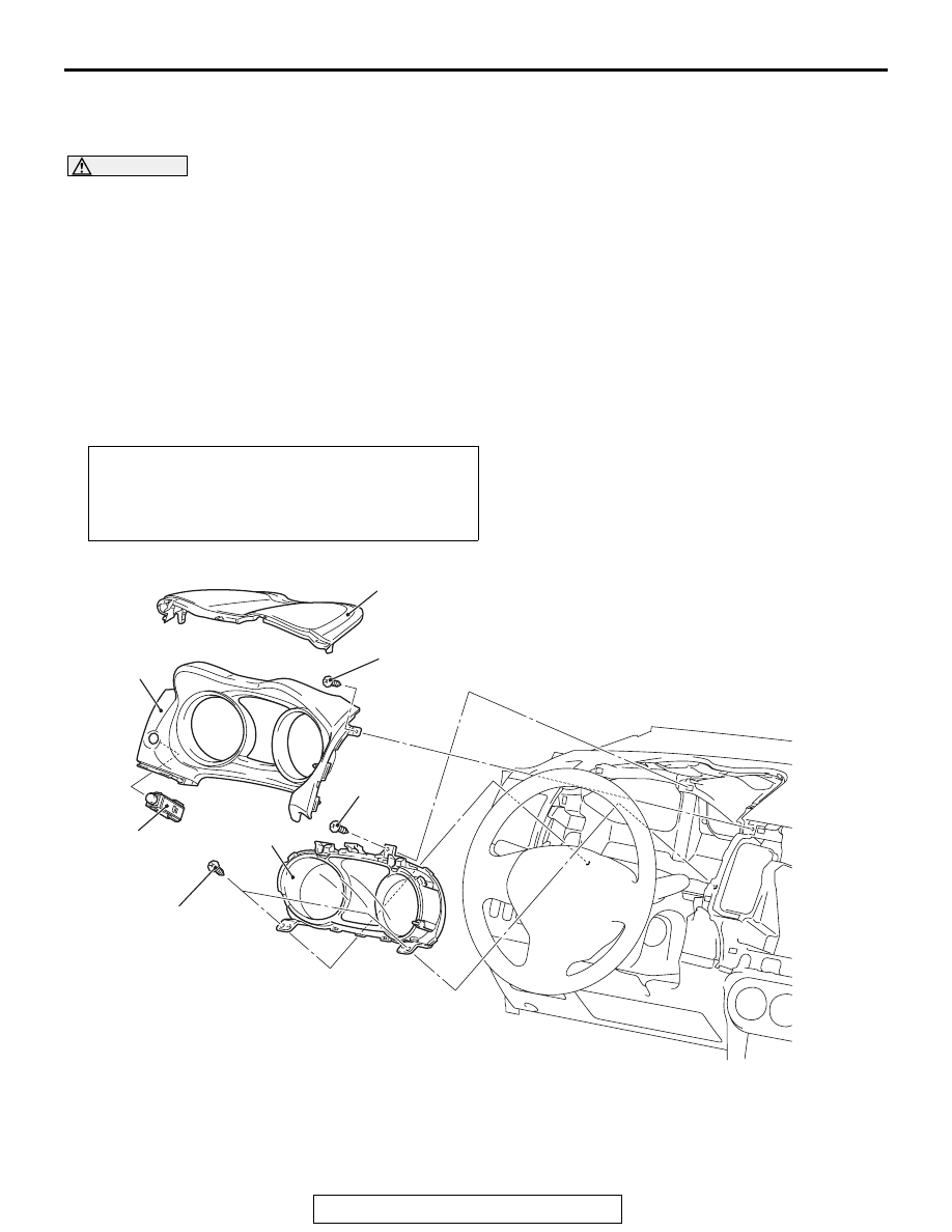
REMOVAL AND INSTALLATION

M1540201700290

CAUTION

When the combination meter is required to be replaced, the current driving distance and number of 
elapsed days must be entered into the meter after the replacement in order to be used for service 
reminder function. Therefore, read "Integrated mileage for reminder," "Integrated days for reminder," 
"Mileage until Extra reminder," "Months until Extra reminder," and "Current Schedule" from the meter 
before the replacement using the special function of scan tool MB991958, and note them. For the 
operation method of scan tool MB991958, refer to 

P.54A-93

. If "Integrated mileage for reminder" or 

"Integrated days for reminder" cannot be read by the scan tool MB991958, follow the method 
described below.

• For the driving distance for check warning, use the driving distance displayed on the multi infor-

mation display.

• For the elapsed days for check warning, calculate the number of elapsed days from the delivery 

date to the customer (service remainder function start date) and current date.

Pre-removal and Post-installation Operation
• Instrument center panel (Refer to GROUP 52A, Instru-

ment Center Panel 

P.52A-7

).

• Instrument panel air outlet garnish lower (LH) (Refer to 

GROUP 52A, Instrument lower Panel 

P.52A-8

).

AC709245

1

3

2

4

AB

2.5 ± 0.5 N·m
23 ± 4 in-lb

2.5 ± 0.5 N·m
23 ± 4 in-lb

2.5 ± 0.5 N·m
23 ± 4 in-lb

Removal Steps 

1.

Combination meter bezel

2.

Instrument meter cluster panel

3.

Combination meter assembly

4.

Multi information meter switch

Removal Steps (Continued)

HEADLIGHT

TSB Revision

CHASSIS ELECTRICAL

54A-102

DISASSEMBLY AND ASSEMBLY

M1540201800220

HEADLIGHT

GENERAL INFORMATION

M1542000100413

• As for headlight assembly, a type with halogen 

bulbs for the high-beam and low-beam and a type 
with a discharge bulb for both high-beam and 
low-beam are established.

• The halogen bulb type headlight assembly 

employs the four-light type integrated with the 
headlight (low-beam), headlight (high-beam), 
front turn-signal light, and position light. The 
dimmed headlight (low-beam) is also used as a 
daytime running light.

• The discharge bulb type headlight assembly 

employs the two-light type integrated with the 
projector type headlight (low-beam/high-beam), 
daytime running light, front turn-signal light, and 
position light, and the headlight manual leveling 
system are adopted. The switching of headlight 
(low-beam/high-beam) is performed by the driv-
ing of light-shield in the projector unit using the 
signal from lighting switch.

AC707877AC

1

2

Disassembly steps 

1.

Combination meter glass

2.

Combination meter

AC709102

Headlight (Low-beam)
<Vehicles without discharge headlight>

Position light

Headlight (High-beam / low-beam)
<Vehicles with discharge headlight>

Headlight (High-beam)
<Vehicles without discharge headlight>

Daytime running light
<Vehicles with discharge headlight>

Front turn-signal light

Headlight
assembly

AC

HEADLIGHT

TSB Revision

CHASSIS ELECTRICAL

54A-103

SERVICE SPECIFICATIONS

M1540100200251

PRECAUTIONS ON HOW TO USE THE HEADLIGHT ASSEMBLY

Be careful with the following items as resin lenses 
are used in the headlight assembly.

• Don't illuminate the headlight for three minutes or 

more when the headlight is covered with scratch 
protector.

• Don't tape the outer lens.

• Don't scratch the outer lens surface with a sharp 

edged special tool.

• Use the specified genuine bulb.

Item

Standard value

Limit

Headlight aiming 
[at 7.62 m (25.0 ft)]

Low-beam 
<Vehicles 
without 
discharge 
headlight>

Vertical 
direction

Horizontal line (H) 

± 50.5 

mm (

± 2.0 inches) (± 0.38 

degrees angle)

Horizontal 
direction

± 126.4 mm (± 5.0 inches) 

(

± 0.95 degrees angle) 

from the axis, which is 
266.1 mm (10.5 inches) (2 
degrees angle) rightward 
from the vertical line (V)

Low-beam 
<Vehicles 
with 
discharge 
headlight>

Vertical 
direction

53.2 mm (2.1 inches) (0.4 
degrees) below horizontal 
line (H). 

± 50.5 mm (± 2.0 

inches) (

± 0.38 degrees 

angle)

Horizontal 
direction

Elbow point intersects the 
vertical line (V). 

± 126.4 

mm (

± 5.0 inches) (± 0.95 

degrees angle)

Headlight intensity cd (at high-beam)

40,000 or more {when a screen 
is set 18.3m(60 ft) ahead of the 
vehicle}

HEADLIGHT

TSB Revision

CHASSIS ELECTRICAL

54A-104

SPECIAL TOOLS

M1540104400116

Tool

Tool number and 
name

Supersession

Application

MB991958

a. MB991824
b. MB991827
c. MB991910
d. MB991911
e. MB991914
f. MB991825
g. MB991826

M.U.T.-III 
sub-assembly

a. Vehicle 

communication 
interface (V.C.I.)

b. M.U.T.-III USB 

cable

c. M.U.T.-III main 

harness A 
(Vehicles with 
CAN 
communication 
system)

d. M.U.T.-III main 

harness B 
(Vehicles 
without CAN 
communication 
system)

e. M.U.T.-III main 

harness C (for 
Daimler 
Chrysler 
models only)

f. M.U.T.-III 

measurement 
adapter

g. M.U.T.-III trigger 

harness

MB991824-KIT
NOTE: G: 
MB991826 
M.U.T.-III Trigger 
Harness is not 
necessary when 
pushing V.C.I. 
ENTER key.

CAUTION

M.U.T.-III main harness A 
(MB991910) should be used. 
M.U.T.-III main harness B and C 
should not be used for this 
vehicle.
DTC, data list and actuator test 
check.

MB991910

MB991826

MB991958

MB991911

MB991914

MB991824

MB991827

MB991825

DO NOT USE

a

b

c

d

e

f

g

DO NOT USE


Content   ..  933  934  935  936   ..