Mitsubishi Evolution X. Manual - part 926
 

  Index      Mitsubishi     Mitsubishi Evolution X - service repair manual 2008 year


Search            


Content   ..  924  925  926  927   ..


Mitsubishi Evolution X. Manual - part 926


COMBINATION METER

TSB Revision

CHASSIS ELECTRICAL

54A-65

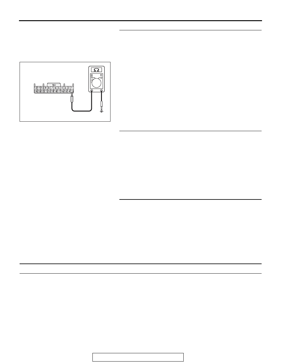
STEP 8. Check the ground circuit to the combination 
meter. Test at combination meter connector C-04.
(1) Disconnect combination meter connector C-04 and 

measure the resistance available at the wiring harness side 
of the connector.

(2) Measure the resistance value between terminal 13 and 

ground.

• The resistance should be 2 ohms or less.

Q: Is the measured resistance 2 ohms or less?

YES : Go to Step 10.
NO :  Go to Step 9.

STEP 9. Check the wiring harness between combination 
meter connector C-04 (terminal 13) and ground.
Q: Is the wiring harness between combination meter 

connector C-04 (terminal 13) and ground in good 
condition?
YES : 
The trouble can be an intermittent malfunction (Refer 

to GROUP 00 

− How to use 

Troubleshooting/inspection Service Points 

− How to 

Cope with Intermittent Malfunction 

P.00-15

).

NO :  Repair the wiring harness.

STEP 10. Retest the system.
Check that the combination meter works normally.
Q: Is the check result satisfactory?

YES : The trouble can be an intermittent malfunction (Refer 

to GROUP 00 

− How to use 

Troubleshooting/inspection Service Points 

− How to 

Cope with Intermittent Malfunction 

P.00-15

).

NO :  Replace the combination meter.

Inspection Procedure 2: The speedometer does not work (the other meters work).

.

TECHNICAL DESCRIPTION (COMMENT)

If only the speedometer does not operate, the 
ASC-ECU and combination meter may have a prob-
lem.

.

TROUBLESHOOTING HINTS

• The ASC-ECU may be defective

• The combination meter may be defective

DIAGNOSIS

Required Special Tools:

• MB991958: Scan Tool (M.U.T.-III Sub Assembly)

• MB991824: Vehicles Communication Interface (V.C.I.)

• MB991827: M.U.T.-III USB Cable

AC608255 BC

Harness side: C-04

COMBINATION METER

TSB Revision

CHASSIS ELECTRICAL

54A-66

• MB991910: M.U.T.-III Main Harness A (Vehicles with 

CAN communication system)

STEP 1. Using scan tool MB991958, diagnose the CAN bus 
line.

CAUTION

To prevent damage to scan tool MB991958, always turn the 
ignition switch to the "LOCK" (OFF) position before con-
necting or disconnecting scan tool MB991958.
(1) Connect scan tool MB991958. Refer to "How to connect the 

Scan Tool (M.U.T.-III) 

P.54A-25

."

(2) Turn the ignition switch to the "ON" position.
(3) Diagnose the CAN bus line.
(4) Turn the ignition switch to the "LOCK" (OFF) position.
Q: Is the CAN bus line found to be normal?

YES : Go to Step 2.
NO :  Repair the CAN bus line (Refer to GROUP 54C, 

Diagnosis 

P.54C-14

).

STEP 2. Using scan tool MB991958, read the combination 
meter diagnostic trouble code.
Check if DTC is set to the combination meter.
Q: Is the DTC set?

YES : Troubleshoot the combination meter (Refer to 

P.54A-28

).

NO :  Go to Step 3.

STEP 3. Using scan tool MB991958, read the ASC-ECU 
diagnostic trouble code.
Check if diagnostic trouble code is set to the ASC.
Q: Is the DTC set?

YES : Troubleshoot the ASC (Refer to GROUP 35C, 

Diagnosis 

P.35C-20

).

NO :  Go to Step 4.

AC608435

Data link connector

MB991827

MB991824

MB991910

AB

COMBINATION METER

TSB Revision

CHASSIS ELECTRICAL

54A-67

STEP 4. Using scan tool MB991958, check data list.
(1) Turn the ignition switch to the "ON" position.
(2) Check the data list on the combination meter.

• Item 80: Speedometer

• Should read vehicle speed.

(3) Turn the ignition switch to the "LOCK" (OFF) position.
Q: Does it read vehicle speed?

YES : Go to Step 5.
NO :  Replace the combination meter.

STEP 5. Using scan tool MB991958, check actuator test.
(1) Turn the ignition switch to the "ON" position.
(2) Conduct the actuator test of the combination meter.

• Item 1: Speedometer

• The speedometer operates up to the set position.

(3) Turn the ignition switch to the "LOCK" (OFF) position.
Q: Is the check result normally?

YES : Go to Step 6.
NO :  Replace the combination meter.

STEP 6. Retest the system.
Check that the speedometer works normally.
Q: Is the check result normal?

YES : The procedure is complete.
NO :  Go to Step 1.

Inspection Procedure 3: The tachometer does not work (the other meters work).

.

TECHNICAL DESCRIPTION (COMMENT)

If only the tachometer does not operate, the ignition 
signal from the engine ECU may not be received or 
the combination meter may have a problem.

.

TROUBLESHOOTING HINTS

• The combination meter may be defective

• The engine control module may be defective

DIAGNOSIS

Required Special Tools:

• MB991958: Scan Tool (M.U.T.-III Sub Assembly)

• MB991824: Vehicles Communication Interface (V.C.I.)

• MB991827: M.U.T.-III USB Cable

• MB991910: M.U.T.-III Main Harness A (Vehicles with 

CAN communication system)

COMBINATION METER

TSB Revision

CHASSIS ELECTRICAL

54A-68

STEP 1. Using scan tool MB991958, diagnose the CAN bus 
line.

CAUTION

To prevent damage to scan tool MB991958, always turn the 
ignition switch to the "LOCK" (OFF) position before con-
necting or disconnecting scan tool MB991958.
(1) Connect scan tool MB991958. Refer to "How to connect the 

Scan Tool (M.U.T.-III) 

P.54A-25

."

(2) Turn the ignition switch to the "ON" position.
(3) Diagnose the CAN bus line.
(4) Turn the ignition switch to the "LOCK" (OFF) position.
Q: Is the CAN bus line found to be normal?

YES : Go to Step 2.
NO :  Repair the CAN bus line (Refer to GROUP 54C, 

Diagnosis 

P.54C-14

).

STEP 2. Using scan tool MB991958, read the combination 
meter diagnostic trouble code.
Check if DTC is set to the combination meter.
Q: Is the DTC set?

YES : Troubleshoot the combination meter (Refer to 

P.54A-28

).

NO :  Go to Step 3.

STEP 3. Using scan tool MB991958, read the MFI 
diagnostic trouble code.
Check if DTC is set to the engine control module.
Q: Is the DTC set?

YES : Troubleshoot the MFI (Refer to GROUP 13A, 

Diagnosis 

P.13A-44

).

NO :  Go to Step 4.

AC608435

Data link connector

MB991827

MB991824

MB991910

AB


Content   ..  924  925  926  927   ..