Mitsubishi Evolution X. Manual - part 824
AC201323 AD
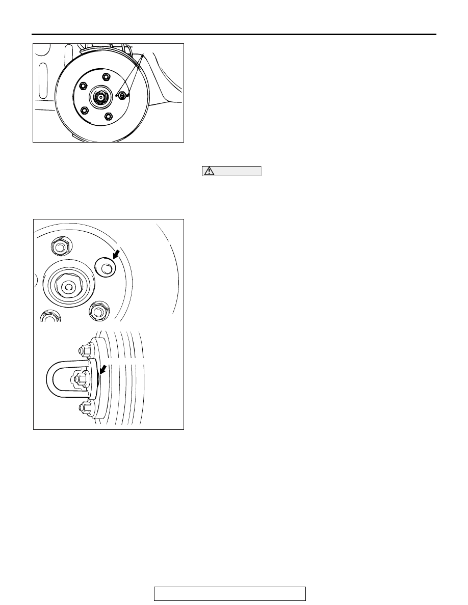
Chalk marks
ON-VEHICLE SERVICE
TSB Revision
BASIC BRAKE SYSTEM
35A-23
(1) Before removing the brake disk, make marks using a
chalk to the stud bolt on the side with the greater runout
and to both sides of the stud bolt.
(2) Check the wheel bearing axial looseness. (Refer to
GROUP 26
− On-vehicle Service, Wheel Bearing End
Play Check
<Front> or GROUP 27
− On-vehicle
Service, Wheel Bearing End Play Check
<Rear>.)
(3) When the looseness is within the limit value, install the
brake disk after changing the phase between the hub and
the brake disk, then check the runout of the brake disk
again.
CAUTION
• After a new brake disk is installed, always grind the
brake disk with on-the-car type brake lathe. If this step
is not carried out, the brake disk run-out exceeds the
specified value, resulting in judder.
•
AC006226 AE
M12 Flat washer
M12 Flat washer
When the on-the-car type lathe is used, first install M12
flat washer on the stud bolt in the brake disk side
according to the figure, and then install the adapter. If
the adapter is installed with M12 flat washer not seated,
the brake disk rotor may be deformed, resulting in inac-
curate grinding.
• Grind the brake disk with all wheel nuts diagonally and
equally tightened to the specified torque 100 N
⋅ m (74
ft-lb). When all numbers of wheel nuts are not used, or
the tightening torque is excessive or not equal, the
brake disk rotor or drum may be deformed, resulting in
judder.
5. If the run-out cannot be corrected by changing the phase of
the brake disk, replace the brake disk or grind it with the
on-the-car type brake lathe ("MAD, DL-8700PF" or
equivalent).