Mitsubishi Evolution X. Manual - part 608


  Index      Mitsubishi     Mitsubishi Evolution X - service repair manual 2008 year


Search            


Content   ..  606  607  608  609   ..


Mitsubishi Evolution X. Manual - part 608


DIAGNOSIS

TSB Revision

WIRELESS CONTROL MODULE (WCM)

42C-49

DTC C1910: Transmitter low battery voltage abnormality 1


DTC C1920: Transmitter low battery voltage abnormality 2


DTC C1930: Transmitter low battery voltage abnormality 3


DTC C1940: Transmitter low battery voltage abnormality 4


DTC C1911: Reception abnormality 1


DTC C1921: Reception abnormality 2


DTC C1931: Reception abnormality 3


DTC C1941: Reception abnormality 4
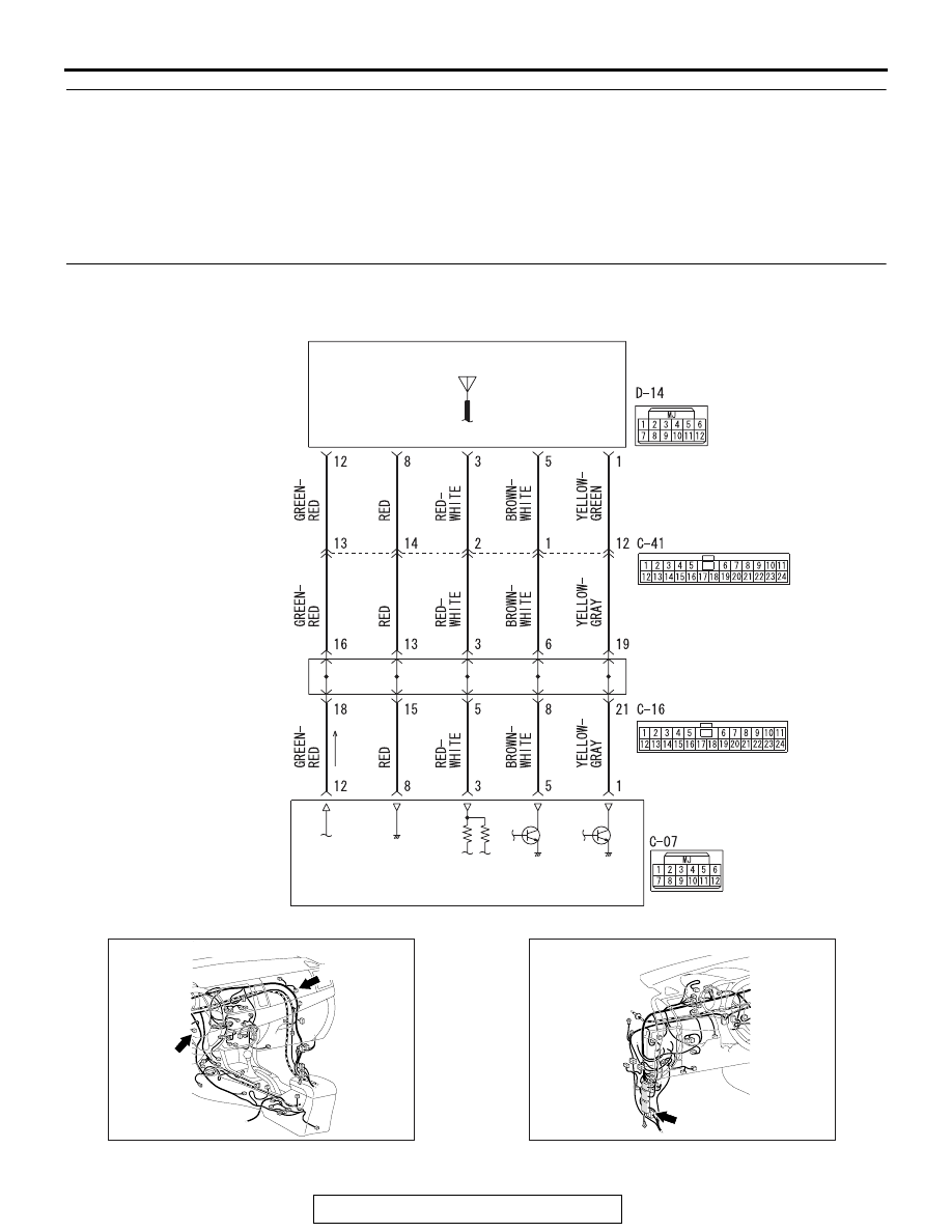
JOINT 
CONNECTOR 
(6)

WIRELESS CONTROL 
MODULE

RECEIVER 
ANTENNA 
ASSEMBLY

RECEIVER

AC709591

AC708951AY

Connectors: C-07, C-16

C-16 (B)

C-07

AC708950BA

Connector: C-41

DIAGNOSIS

TSB Revision

WIRELESS CONTROL MODULE (WCM)

42C-50

CAUTION

If there is any problem in the CAN bus lines, an incorrect 
diagnostic trouble code may be set. Prior to this diagno-
sis, diagnose the CAN bus lines (Refer to GROUP 54C, 
Trouble code diagnosis 

P.54C-14

).

.

DTC SET CONDITION

DTC C1910, C1920, C1930, C1940

• When the reception abnormality warning is activated 

because of the low battery voltage of the TPMS transmitter.

DTC C1911, C1921, C1931, C1941

• When WCM cannot receive the signals from the TPMS 

transmitters while driving for about 20 minuites, this code is 
set.

.

TROUBLESHOOTING HINTS

The most likely causes for this DTC to set are:

• Low battery that is incorporated into the TPMS transmitter

• Damaged wiring harness and connector

• Registered IDs unmatched

• Malfunction of Receiver antenna assembly

• Malfunction of TPMS transmitter

• Malfunction of WCM

DIAGNOSIS

Required Special Tools:

• MB991958 Scan Tool (M.U.T.-III Sub Assembly)

• MB991824: Vehicle Communication Interface (V.C.I.)

• MB991827 M.U.T.-III USB Cable

• MB991910 M.U.T.-III Main Harness A 

STEP 1. M.U.T.-III CAN bus diagnostics
Use scan tool to diagnose the CAN bus lines.
Q: Is the check result normal?

YES : Then go to Step 3.
NO :  Repair the CAN bus lines (Refer to GROUP 54C 

− 

CAN Bus Diagnostics table 

P.54C-240

). Then go to 

Step 2.

AC708955AM

Connector: D-14

DIAGNOSIS

TSB Revision

WIRELESS CONTROL MODULE (WCM)

42C-51

STEP 2. Diagnostic trouble code recheck after resetting 
CAN bus lines
Q: Is the DTC C1910, C1920, C1930, C1940, C1911, C1921, 

C1931 or C1941 set?
YES (When DTC C1911, C1921, C1931 and C1941 are 
set) :  
Go to Step 3.
YES (When DTC C1911, C1921, C1931 or C1941 is set) : 

Go to Step 7.

YES (When DTC C1910, C1920, C1930, C1940, C1911, 
C1921, C1931 and C1941 are set) : 
Replace all TPMS 

transmitters, and then register the ID codes. (Refer to 

P.42C-114

.) Then go to Step 8.

NO :  The procedure is complete.

STEP 3. Connector check: C-07 WCM connector, C-16 joint 
connector, C-41 intermediate connector, and D-14 receiver 
antenna assembly connector
Q: Is the check result normal?

YES : Go to Step 4.
NO :  Repair or replace the difective connector, and then 

register the ID codes. (Refer to 

P.42C-114

.) Then go 

to Step 8.

DIAGNOSIS

TSB Revision

WIRELESS CONTROL MODULE (WCM)

42C-52

STEP 4. Wiring harness check between C-07 WCM 
connector and D-14 receiver antenna assembly connector.
(1) Disconnect C-07 WCM connector and D-14 receiver 

antenna assembly connector.

(2) Measure at the connector side of the D-14 receiver antenna 

assembly.

(3) Measure the resistance between the D-14 receiver antenna 

assembly terminals.

Terminal No.1 

− body ground.

Terminal No.3 

− body ground.

Terminal No.5 

− body ground.

Terminal No.8 

− body ground.

AC709322 BY

Harness side: D-14

AC709322 BZ

Harness side: D-14

AC709322 CA

Harness side: D-14

AC709322 CB

Harness side: D-14


Content   ..  606  607  608  609   ..