Mitsubishi Evolution X. Manual - part 234
 

  Index      Mitsubishi     Mitsubishi Evolution X - service repair manual 2008 year


Search            


Content   ..  232  233  234  235   ..


Mitsubishi Evolution X. Manual - part 234


THERMOSTAT

TSB Revision

ENGINE COOLING

14-23

REMOVAL SERVICE POINT

.

<<A>> RADIATOR LOWER HOSE DISCONNEC-
TION

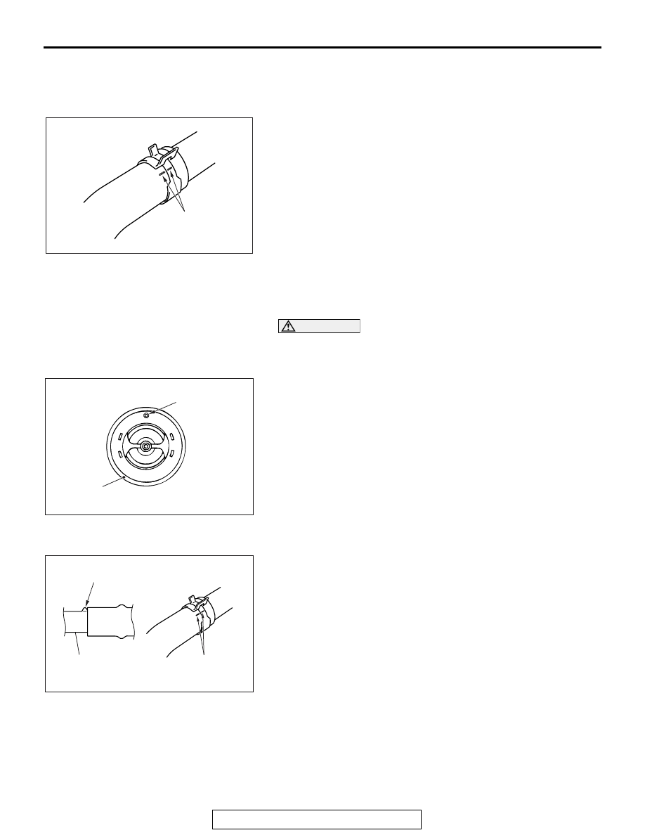
Make mating marks on the radiator hose and the hose clamp. 
Disconnect the radiator hose.

INSTALLATION SERVICE POINTS

.

>>A<< THERMOSTAT INSTALLATION

CAUTION

Make absolutely sure that no oil adheres to the rubber ring 
of the thermostat. Also do not fold or scratch the rubber 
ring during installation.
Install the thermostat so that the jiggle valve is facing straight 
up. Be careful not to fold or scratch the rubber ring.

.

>>B<< RADIATOR LOWER HOSE CONNECTION

1. Insert each hose as far as the projection of the water inlet 

fitting.

2. Align the mating marks on the radiator hose and hose 

clamp, and then connect the radiator hose.

AC200641AD

Mating marks

AC000279

Jiggle valve

Rubber ring

AD

AC200642

Mating
marks

Projection

Water inlet 
fitting 

AX

THERMOSTAT

TSB Revision

ENGINE COOLING

14-24

INSPECTION

M1141002501055

.

THERMOSTAT CHECK

1. Immerse the thermostat in water, and heat the water while 

stirring. Check the thermostat valve opening temperature.

Standard value: Valve opening temperature: 76.5 

± 

1.5

° C (170 ± 3° F)

2. Check that the amount of valve lift is at the standard value 

when the water is at the full-opening temperature.
NOTE: Measure the valve height when the thermostat is 
fully closed, and use this measurement to compare the 
valve height when the thermostat is fully open.

Standard value:

Full-opening temperature:90

° C (194° F)

Amount of valve lift: 8.5 mm (0.33 inch) or more

ACX00400

ACX00401AD

Valve lift

WATER PUMP

TSB Revision

ENGINE COOLING

14-25

WATER PUMP

REMOVAL AND INSTALLATION

M1141002701800

Pre-removal operation
• Engine Coolant Draining (Refer to 

P.14-17

).

• Drive Belt Removal (Refer to GROUP 11A, Crankshaft 

Pulley 

P.11A-21

).

• Engine Upper Cover Removal (Refer to GROUP 16, Igni-

tion System 

− Ignition Coil 

P.16-39

).

• Strut Tower Bar Removal (Refer to GROUP 42A, Strut 

Tower Bar 

P.42A-15

).

Post-installation operation
• Drive Belt Installation (Refer to GROUP 11A, Crankshaft 

Pulle

P.11A-21

).

• Drive Belt Tension Check (Refer to GROUP 11A, Engine 

Adjustment 

− Drive Belt Tension Check and Adjustment 

P.11A-8

).

• Strut Tower Bar Installation (Refer to GROUP 42A, Strut 

Tower Bar 

P.42A-15

).

• Engine Upper Cover Installation (Refer to GROUP 16, 

Ignition System 

− Ignition Coil 

P.16-39

).

• Engine Coolant Refilling (Refer to 

P.14-17

).

AC705835

24 ± 3 N·m
18 ± 2 ft-lb

2

1

6

7

N

N

9.0 ± 1.0 N·m
80 ± 9 in-lb

3

5

4

AC

24 ± 3 N·m
18 ± 2 ft-lb

24 ± 3 N·m
18 ± 2 ft-lb

Removal steps 

1.

Water pump pulley mounting bolts

2.

Water pump inlet pipe mounting 
nuts

3.

Water pump pulley and water 
pump assembly

4.

Water pump pulley

5.

Water pump

6.

Cooling water line gasket

7.

Water pump gasket

Removal steps (Continued)

WATER HOSE AND WATER PIPE

TSB Revision

ENGINE COOLING

14-26

WATER HOSE AND WATER PIPE

REMOVAL AND INSTALLATION

M1141003302068

Pre-removal operation
• Engine Coolant Draining (Refer to 

P.14-17

).

• Engine Upper Cover Removal (Refer to GROUP 16, Igni-

tion System 

− Ignition Coil 

P.16-39

).

• Air Cleaner Assembly Removal (Refer to GROUP 15, Air 

Cleane

P.15-10

).

• Thermostat Removal (Refer to 

P.14-22

).

Post-installation operation
• Thermostat Installation (Refer to 

P.14-22

).

• Air Cleaner Assembly Installation (Refer to GROUP 15, 

Air Cleaner 

P.15-10

).

• Engine Upper Cover Installation (Refer to GROUP 16, 

Ignition System 

− Ignition Coil 

P.16-39

).

• Engine Coolant Refilling (Refer to 

P.14-17

).

AC705836

11 ± 1 N·m
98 ± 8 in-lb

24 ± 3 N·m
18 ± 2 ft-lb

24 ± 3 N·m
18 ± 2 ft-lb

42 ± 7 N·m
31 ± 5 ft-lb

9.5 ± 1.5 N·m
84 ± 13 in-lb

24 ± 3 N·m
18 ± 2 ft-lb

24 ± 3 N·m
18 ± 2 ft-lb

30 ± 9 N·m
22 ± 7 ft-lb

10 ± 2 N·m
89 ± 17 in-lb

5.0 ± 1.0 N·m
45 ± 8 in-lb

1

2

3

4

5

6

7

8

9

10

10

11

12

13

14

15

22

16

17

18

19

20

21

23

N

N

N

N

N

AC

22

10 ± 2 N·m
89 ± 17 in-lb

11 ± 1 N·m
98 ± 8 in-lb

24 ± 3 N·m
18 ± 2 ft-lb

Thermostat case removal 
steps 

<<A>>

>>D<<

1.

Radiator upper hose

2.

Cooling water outlet hose fitting

3.

Cooling water outlet hose fitting 
gasket

4.

Cooling water line hose

5.

Cooling water line hose

6.

Engine coolant temperature 
sensor connector connection

7.

Heater hose connection

8.

Ground cable connection

9.

Control wiring harness 
connection

10. Harness bracket

11. Turbocharger water feed hose
12. Turbocharger water feed pipe
13. Gasket
14. Fuel return hose connection

<<B>>

>>B<<

15. Fuel high-pressure hose 

connection

16. Thermostat case
17. Thermostat case gasket

Water pump inlet pipe removal 
steps 

16. Thermostat case
17. Thermostat case gasket

Thermostat case removal steps 
(Continued)


Content   ..  232  233  234  235   ..