Mitsubishi Evolution X. Manual - part 217
 

  Index      Mitsubishi     Mitsubishi Evolution X - service repair manual 2008 year


Search            


Content   ..  215  216  217  218   ..


Mitsubishi Evolution X. Manual - part 217


AUTO-CRUISE CONTROL

TSB Revision

ENGINE AND EMISSION CONTROL

17-37

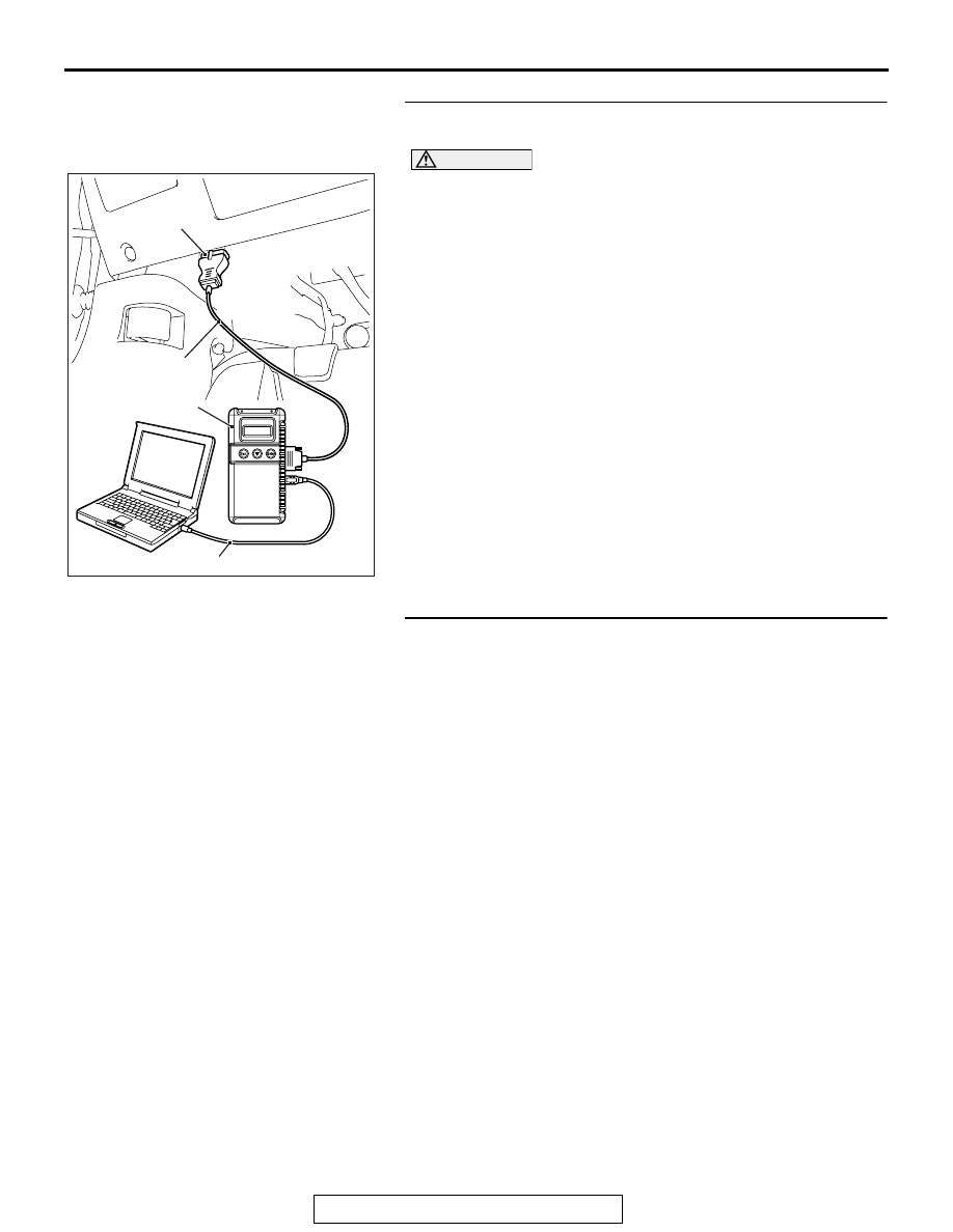
STEP 1. Using scan tool MB991958, check for MFI system 
DTC.

AC608435

Data link connector

MB991827

MB991824

MB991910

AB

CAUTION

To prevent damage to scan tool MB991958, always turn the 
ignition switch to the "LOCK" (OFF) position before con-
necting or disconnecting scan tool MB991958.
(1) Connect scan tool MB991958 to the data link connector 

(Refer to 

P.17-10

).

(2) Turn the ignition switch to the "ON" position.
(3) Check for MFI system DTC (Refer to GROUP 13A, MFI 

Diagnosis 

− Diagnostic Function 

P.13A-9

).

(4) Turn the ignition switch to the "LOCK" (OFF) position.
(5) Disconnect scan tool MB991958.
Q: Is any DTC set?

YES : Diagnose the MFI system (Refer to GROUP 13A, MFI 

Diagnosis 

− Diagnostic Trouble Code Chart 

P.13A-44

). Then go to Step 3.

NO :  Go to Step 2.

STEP 2. Read the cruise control system DTC.
(1) Disconnect the negative (

−) battery terminal, to erase the 

DTC of the cruise control system.

(2) Connect the negative (

−) battery terminal.

(3) Turn the ignition switch to the "ON" position, and press the 

"ON/OFF" switch to turn the cruise control system to ON 
(turn on the "CRUISE" indicator light).

(4) After turning the cruise control system to ON, when 2 

minutes or more has elapsed without operating the cruise 
control switches, read the DTC of the cruise control system 
(Refer to 

P.17-10

).

Q: Is DTC 23 set?

YES : Replace the ECM [Refer to GROUP 13A, Engine 

Control Module (ECM) 

P.13A-920

]. When the ECM is 

replaced, register the encrypted code (Refer to 
GROUP 42C, Diagnosis 

− ID Code Registration 

Judgment Table 

P.42C-9

). Then go to Step 3.

NO :  It can be assumed that this malfunction is intermittent 

(Refer to GROUP 00, How to Use 
Troubleshooting/Inspection Service Points 

− How to 

Cope with Intermittent Malfunction 

P.00-15

).

AUTO-CRUISE CONTROL

TSB Revision

ENGINE AND EMISSION CONTROL

17-38

STEP 3. Read the cruise control system DTC.
(1) Disconnect the negative (

−) battery terminal, to erase the 

DTC of the cruise control system.

(2) Connect the negative (

−) battery terminal.

(3) Turn the ignition switch to the "ON" position, and press the 

"ON/OFF" switch to turn the cruise control system to ON 
(turn on the "CRUISE" indicator light).

(4) After turning the cruise control system to ON, when 2 

minutes or more has elapsed without operating the cruise 
control switches, read the DTC of the cruise control system 
(Refer to 

P.17-10

).

Q: Is DTC 23 set?

YES : Return to Step 1.
NO :  The procedure is complete.

SYMPTOM CHART

M1172002301091

Symptom

Inspection 
procedure 
number

Reference page

Communication with 
scan tool is not 
possible

Communication with the ECM only is 
impossible

GROUP 13A, MFI 
Diagnosis, 
Symptom 
Procedures 

− 

Inspection 
Procedure 1 

P.13A-737

Cruise control is not 
cancelled.

When brake pedal is depressed

1

P.17-38

When clutch pedal is depressed <M/T>

2

P.17-41

When shift lever is moved to "N" position 
<TC-SST>

3

P.17-44

When "CANCEL" switch is turned ON

4

P.17-47

Cruise control cannot be set ("COAST/SET" or "ACC/RES" switch 
operation is not available).

5

P.17-48

Hunting (repeated acceleration and deceleration) occurs at the 
set vehicle speed.

6

P.17-53

When "ON/OFF" switch is turned ON, "CRUISE" indicator light 
inside combination meter does not illuminate. (However, cruise 
control system is normal).

7

P.17-56

SYMPTOM PROCEDURES

INSPECTION PROCEDURE 1: When the Brake Pedal is Depressed, Cruise Control System is not 
Cancelled.

.

COMMENT

• Malfunction of CAN bus line.

• The stoplight switch circuit is suspected.

.

TROUBLESHOOTING HINTS (THE MOST 
LIKELY CAUSES FOR THIS CASE:)

• Malfunction of CAN bus system.

• Damaged harness or connector.

AUTO-CRUISE CONTROL

TSB Revision

ENGINE AND EMISSION CONTROL

17-39

• Malfunction of the stoplight switch.

• Malfunction of the ETACS-ECU.

• Malfunction of the ECM.

DIAGNOSIS

Required Special Tools:

• MB991958: Scan Tool (M.U.T.-III Sub Assembly)

• MB991824: V.C.I.

• MB991827: M.U.T.-III USB Cable

• MB991910: M.U.T.-III Main Harness A

• MB991223: Harness Set

• MB992006: Extra Fine Probe

CAUTION

• If there is any problem in the CAN bus lines, an incor-

rect DTC may be set. Prior to this diagnosis, diagnose 
the CAN bus lines.

• Whenever the ECM is replaced, ensure that the CAN 

bus lines are normal.

STEP 1. Using scan tool MB991958, diagnose the CAN bus 
line.

AC608435

Data link connector

MB991827

MB991824

MB991910

AB

CAUTION

To prevent damage to scan tool MB991958, always turn the 
ignition switch to the "LOCK" (OFF) position before con-
necting or disconnecting scan tool MB991958.
(1) Connect scan tool MB991958 to the data link connector 

(Refer to 

P.17-10

).

(2) Turn the ignition switch to the "ON" position.
(3) Diagnose the CAN bus line (Refer to 

P.17-10

).

(4) Turn the ignition switch to the "LOCK" (OFF) position.
(5) Disconnect scan tool MB991958.
Q: Is the check result satisfactory?

YES : Go to Step 2
NO :  Repair the CAN bus lines (Refer to GROUP 54C, 

Diagnosis 

− Can Bus Diagnostic Chart 

P.54C-14

). 

Then go to Step 4.

AUTO-CRUISE CONTROL

TSB Revision

ENGINE AND EMISSION CONTROL

17-40

STEP 2. Using scan tool MB991958, check data list item 74: 
Brake light switch and item 89: Normally closed brake 
switch.
(1) Connect scan tool MB991958 to the data link connector 

(Refer to 

P.17-10

).

(2) Turn the ignition switch to the "ON" position.
(3) Set scan tool MB991958 to data reading mode for cruise 

control system (Refer to 

P.17-10

).

• Item 74: Brake light switch.

• When the brake pedal is depressed, the display on 

scan tool MB991958 should be "ON".

• When the brake pedal is released, the display on 

scan tool MB991958 should be "OFF".

• Item 89: Normally closed brake switch.

• When the brake pedal is depressed, the display on 

scan tool MB991958 should be "ON".

• When the brake pedal is released, the display on 

scan tool MB991958 should be "OFF".

(4) Turn the ignition switch to the "LOCK" (OFF) position.
(5) Disconnect scan tool MB991958.
Q: Is the switch operating properly?

YES : Go to Step 3
NO :  Refer to 

P.17-27

, Diagnostic Trouble Code 

Procedures 

− DTC 22: Stoplight Switch System. Then 

go to Step 4.

STEP 3. Check the symptoms.
Q: When the brake pedal is depressed, cruise control 

system is cancelled?
YES : 
It can be assumed that this malfunction is intermittent 

(Refer to GROUP 00, How to Use 
Troubleshooting/Inspection Service Points 

− How to 

Cope with Intermittent Malfunction 

P.00-15

).

NO :  Replace the ECM [Refer to GROUP 13A, Engine 

Control Module (ECM) 

P.13A-920

]. When the ECM is 

replaced, register the encrypted code (Refer to 
GROUP 42C, Diagnosis 

− ID Code Registration 

Judgment Table 

P.42C-9

). Then go to Step 4.

STEP 4. Check the symptoms.
Q: When the brake pedal is depressed, cruise control 

system is cancelled?
YES : 
The procedure is complete.
NO :  Return to Step 1.


Content   ..  215  216  217  218   ..