Mitsubishi Evolution X. Manual - part 172
 

  Index      Mitsubishi     Mitsubishi Evolution X - service repair manual 2008 year


Search            


Content   ..  170  171  172  173   ..


Mitsubishi Evolution X. Manual - part 172


ON-VEHICLE SERVICE

TSB Revision

ENGINE MECHANICAL

11A-19

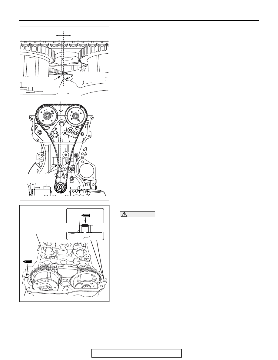
6. Check the end top point "A" of timing chain cross section 

surface and the point of chain elongation indicator which is 
fixed in Step 5. When the end top point "A" of timing chain is 
positioned at the left-hand side of chain elongation indicator, 
it is unnecessary to replace the timing chain because the 
timing chain is within the specified length. When the end top 
point "A" of timing chain is positioned at the right-hand side 
of chain elongation indicator, it is necessary to replace the 
timing chain because the timing chain elongates more than 
the specified length.

7. Install the upper chain guide.

CAUTION

• Completely clean the old FIPG remaining in the clear-

ance between the mating parts.

• Install the cylinder head cover within 3 minutes of 

applying the liquid gasket.

8. Apply a 4 mm diameter bead of liquid gasket to the point 

shown in the illustration.

Liquid gasket: THREE BOND 1217G or equivalent 
product.

AK703287AC

Replace

Unnecessary to
replce

Position of visual line

Visual line

End gear face of
timing chain "A"

End gear face of
timing chain "A"

Chain elongation
indicator

AK

701438

Cylinder head

Timing chain case assembly

AD

φ 4.0 mm

(0.16 in)

φ 4.0 mm (0.16 in)

2.0 mm
(0.08 in)

2.0 mm
(0.08 in)

ON-VEHICLE SERVICE

TSB Revision

ENGINE MECHANICAL

11A-20

9. Installing the cylinder head cover, tighten the tightening bolt 

according to the following procedures.

a. Temporarily tighten the tightening bolt in the order shown in 

the illustration.
Tightening torque: 3.0 

± 1.0 N⋅ m

b. Tighten the tightening bolt to the specified torque in the 

order shown in the illustration.
Tightening torque: 5.5 

± 0.5 N⋅ m

10.Install the ignition coil.
11.Use the scan tool MB991958 to select the timing chain 

maintenance. Initialize the learning value. Refer to 
GROUP00, General 

− Precautions before service − Timing 

chain maintenance 

P.00-33

.

NOTE: Carry out the initialization even if the amount of timing 
chain elongation is normal. As a result of this, it is necessary to 
replace the timing chain before the timing chain interferes with 
the other components when the next warning lamp illuminates 
or the diagnosis code No. P0012 is output. 

AK502760AD

10

16

15

14

17

18

1

3

4

11

12

9

5

2

6

7

8

13

CRANKSHAFT PULLEY

TSB Revision

ENGINE MECHANICAL

11A-21

CRANKSHAFT PULLEY

REMOVAL AND INSTALLATION

M1112001602052

Required Special Tools:

• MB990767: Front Hub and Flange End Yoke 

Holder

• MD998719: Pin

Pre-removal operation
• Engine Room Under Cover Front A, B, Engine Room 

Under Cover Center and Engine Room Side Cover (RH) 

Removal (Refer to GROUP 51, Under Cover 

P.51-16

).

• Radiator Condenser Tank Bracket Removal (Refer to 

GROUP 14, Radiator 

P.14-31

).

Post-installation operation
• Drive Belt Tension Check (Refer to 

P.11A-8

).

• Radiator Condenser Tank Bracket Installation (Refer to 

GROUP 14, Radiator 

P.14-31

).

• Engine Room Under Cover Front A, B, Engine Room 

Under Cover Center and Engine Room Side Cover (RH) 

Installation (Refer to GROUP 51, Under Cover 

P.51-16

).

AC704354AC

1

2

3

4

to 0 N·m to

250 N·m
184 ft-lb

to +60˚

110 N·m
81 ft-lb

(Engine oil)

Removal steps 

<<

A

>>

>>

B

<<

1.

Drive belt

<<

B

>>

>>

A

<<

2.

Crankshaft pulley center bolt

<<

B

>>

>>

A

<<

3.

Crankshaft pulley washer

Engine mounting bracket (Refer 
to GROUP 32, Engine Mounting 

P.32-4

)

>>

A

<<

4.

Crankshaft pulley

Removal steps (Continued)

CRANKSHAFT PULLEY

TSB Revision

ENGINE MECHANICAL

11A-22

REMOVAL SERVICE POINTS

.

<<A>> DRIVE BELT REMOVAL

To introduce the serpentine drive system with the drive belt 
auto-tensioner, the following operations will be required.

CAUTION

To reuse the drive belt, draw an arrow indicating the rotat-
ing direction on the back of the belt using chalk to install 
the same direction.
1. Rotate the pulley bolt of the auto-tensioner counterclockwise 

with an offset wrench [45

° , a long offset wrench (5/8 x 11/16 

inches) recommended] and insert the hexagon wrench into 
the auto-tensioner hole to fix the auto-tensioner.

2. Remove the drive belt.

.

<<B>> CRANKSHAFT PULLEY CENTER 
BOLT/CRANKSHAFT PULLEY WASHER 
REMOVAL

1. Hold the crankshaft drive sprocket with special tools 

MB990767 and MD998719.

2. Loosen the crankshaft pulley center bolt and remove the 

crankshaft pulley center bolt and crankshaft pulley washer.

AC506731 AD

Auto-tensioner 

AC511067

AC

Auto-tensioner

Pulley bolt

L-shaped 
hexagon 
wrench

AC506738

AC

MB990767

MD998719

Crankshaft pulley


Content   ..  170  171  172  173   ..