Mitsubishi Evolution X. Manual - part 1141


  Index      Mitsubishi     Mitsubishi Evolution X - service repair manual 2008 year


Search            


Content   ..  1139  1140  1141  1142   ..


Mitsubishi Evolution X. Manual - part 1141


DIAGNOSIS

TSB Revision

CONTROLLER AREA NETWORK (CAN)

54C-199

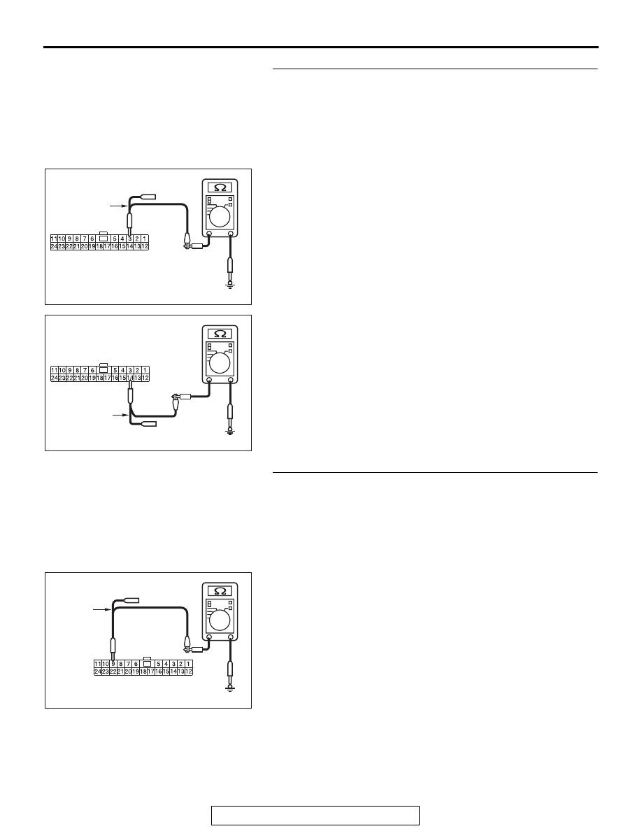
STEP 2. Check the wiring harness between joint connector 
(CAN1) C-105 and combination meter connector C-04 for a 
short to ground. Measure the resistance at joint connector 
(CAN1) C-105.
(1) Disconnect joint connector (CAN1), and measure the 

resistance at the wiring harness side of joint connector 
(CAN1).

(2) Measure the resistance between joint connector (CAN1) 

terminal 3 and body ground.

OK: 1 kilo ohm or more

(3) Measure the resistance between joint connector (CAN1) 

terminal 14 and body ground.

OK: 1 kilo ohm or more

Q: Do all the resistances measure 1 kilo ohm or more?

YES (vehicles with KOS) : Go to Step 3.
YES (vehicles with WCM) : Go to Step 4.
NO (vehicles with KOS or WCM) : Go to Step 48.

STEP 3. Check the wiring harness between joint connector 
(CAN1) C-105 and KOS-ECU connector C-05 for a short to 
ground. Measure the resistance at joint connector (CAN1) 
C-105.
(1) Disconnect joint connector (CAN1), and measure the 

resistance at the wiring harness side of joint connector 
(CAN1).

(2) Measure the resistance between joint connector (CAN1) 

terminal 9 and body ground.

OK: 1 kilo ohm or more

AC608179

TEST 
HARNESS

Harness side: C-105

BY

AC608179

Harness side: C-105

BZ

TEST 
HARNESS

AC608179

TEST 
HARNESS

Harness side: C-105

CA

DIAGNOSIS

TSB Revision

CONTROLLER AREA NETWORK (CAN)

54C-200

(3) Measure the resistance between joint connector (CAN1) 

terminal 22 and body ground.

OK: 1 kilo ohm or more

Q: Do all the resistances measure 1 kilo ohm or more?

YES : Go to Step 5.
NO :  Go to Step 49.

STEP 4. Check the wiring harness between joint connector 
(CAN1) C-105 and WCM connector C-07 for a short to 
ground. Measure the resistance at joint connector (CAN1) 
C-105.
(1) Disconnect joint connector (CAN1), and measure the 

resistance at the wiring harness side of joint connector 
(CAN1).

(2) Measure the resistance between joint connector (CAN1) 

terminal 7 and body ground.

OK: 1 kilo ohm or more

(3) Measure the resistance between joint connector (CAN1) 

terminal 20 and body ground.

OK: 1 kilo ohm or more

Q: Do all the resistances measure 1 kilo ohm or more?

YES : Go to Step 5.
NO :  Go to Step 50.

AC608179

Harness side: C-105

CB

TEST 
HARNESS

AC608179

TEST 
HARNESS

Harness side: C-105

CC

AC608179

Harness side: C-06

CD

TEST 
HARNESS

DIAGNOSIS

TSB Revision

CONTROLLER AREA NETWORK (CAN)

54C-201

STEP 5. Check the wiring harness between joint connector 
(CAN1) C-105 and SRS-ECU connector C-37 for a short to 
ground. Measure the resistance at joint connector (CAN1) 
C-105.
(1) Disconnect joint connector (CAN1), and measure the 

resistance at the wiring harness side of joint connector 
(CAN1).

(2) Measure the resistance between joint connector (CAN1) 

terminal 8 and body ground.

OK: 1 kilo ohm or more

(3) Measure the resistance between joint connector (CAN1) 

terminal 21 and body ground.

OK: 1 kilo ohm or more

Q: Do all the resistances measure 1 kilo ohm or more?

YES : Go to Step 6.
NO :  Go to Step 51.

STEP 6. Check the wiring harness between joint connector 
(CAN1) C-105 and occupant classification-ECU connector 
D-39-2 for a short to ground. Measure the resistance at 
joint connector (CAN1) C-105.
(1) Disconnect joint connector (CAN1), and measure the 

resistance at the wiring harness side of joint connector 
(CAN1).

(2) Measure the resistance between joint connector (CAN1) 

terminal 11 and body ground.

OK: 1 kilo ohm or more

AC608179

TEST 
HARNESS

Harness side: C-105

CE

AC608179

Harness side: C-105

CF

TEST 
HARNESS

AC608179

TEST 
HARNESS

Harness side: C-105

CG

DIAGNOSIS

TSB Revision

CONTROLLER AREA NETWORK (CAN)

54C-202

(3) Measure the resistance between joint connector (CAN1) 

terminal 24 and body ground.

OK: 1 kilo ohm or more

Q: Do all the resistances measure 1 kilo ohm or more?

YES (vehicles without hands free system) : Go to Step 8.
YES (vehicles with hands free system) : Go to Step 7.
NO  :  Go to Step 52.

STEP 7. Check the wiring harness between joint connector 
(CAN1) C-105 and hands free module connector C-11 for a 
short to ground. Measure the resistance at joint connector 
(CAN1) C-105.
(1) Disconnect joint connector (CAN1), and measure the 

resistance at the wiring harness side of joint connector 
(CAN1).

(2) Measure the resistance between joint connector (CAN1) 

terminal 10 and body ground.

OK: 1 kilo ohm or more

(3) Measure the resistance between joint connector (CAN1) 

terminal 23 and body ground.

OK: 1 kilo ohm or more

Q: Do all the resistances measure 1 kilo ohm or more?

YES : Go to Step 8.
NO :  Go to Step 53.

AC608179

Harness side: C-105

CH

TEST 
HARNESS

AC608179

TEST 
HARNESS

Harness side: C-105

CI

AC608179

Harness side: C-105

CJ

TEST 
HARNESS


Content   ..  1139  1140  1141  1142   ..