Mitsubishi Evolution X. Manual - part 1071


  Index      Mitsubishi     Mitsubishi Evolution X - service repair manual 2008 year


Search            


Content   ..  1069  1070  1071  1072   ..


Mitsubishi Evolution X. Manual - part 1071


ETACS

TSB Revision

CHASSIS ELECTRICAL

54A-645

STEP 1. Check key reminder switch connector C-211 for 
loose, corroded or damaged terminals, or terminals 
pushed back in the connector.
Q: Is key reminder switch connector C-211 in good 

condition?
YES : 
Go to Step 2.
NO :  Repair or replace the damaged component(s) (Refer 

to GROUP 00E, Harness Connector Inspection 

P.00E-2

). Check that the input signal of key reminder 

switch is normal.

STEP 2. Check the key reminder switch.
Disconnect key reminder switch connector C-211. Then check 
continuity between terminals.

Q: Is the key reminder switch in good condition?

YES : Go to Step 3.
NO :  Replace the key reminder switch. Check that the input 

signal of key reminder switch is normal.

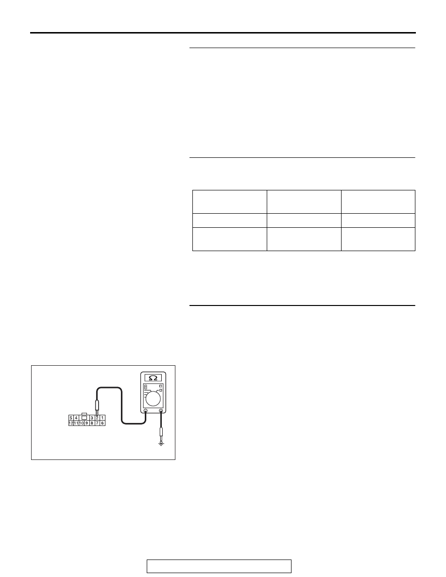
STEP 3. Check the ground circuit to the key reminder 
switch. Measure the resistance at key reminder switch 
connector C-211.
(1) Disconnect key reminder switch connector C-211 and 

measure the resistance available at the wiring harness side 
of the connector.

(2) Measure the resistance value between terminal 2 and 

ground.

• The resistance should be 2 ohms or less.

Q: Is the measured resistance 2 ohms or less?

YES : Go to Step 5.
NO :  Go to Step 4.

Ignition key

Tester connection Specified 

condition

Removed

− 3

Open circuit

Inserted

− 3

Continuity exists 


(2 ohms or less)

AC709322 AN

Harness side: C-211

ETACS

TSB Revision

CHASSIS ELECTRICAL

54A-646

STEP 4. Check the wiring harness between key reminder 
switch connector C-211 (terminal 2) and ground.
Check the ground wires for open circuit.
Q: Is the wiring harness between key reminder switch 

connector C-211 (terminal 2) and ground in good 
condition?
YES : 
No action is necessary and testing is complete.
NO :  The wiring harness may be damaged or the 

connector(s) may have loose, corroded or damaged 
terminals, or terminals pushed back in the connector. 
Repair the wiring harness as necessary. Check that 
the input signal of key reminder switch is normal.

STEP 5. Check ETACS-ECU connector C-315 for loose, 
corroded or damaged terminals, or terminals pushed back 
in the connector.
Q: Is ETACS-ECU connector C-315 in good condition?

YES : Go to Step 6.
NO :  Repair or replace the damaged component(s) (Refer 

to GROUP 00E, Harness Connector Inspection 

P.00E-2

). Check that the input signal of key reminder 

switch is normal.

STEP 6. Check the wiring harness between key reminder 
switch connector C-211 (terminal 3) and ETACS-ECU 
connector C-315 (terminal 13).
Check the output lines for open circuit and short circuit.
Q: Is the wiring harness between key reminder switch 

connector C-211 (terminal 3) and ETACS-ECU connector 
C-315 (terminal 13) in good condition?
YES : 
Go to Step 7.
NO :  The wiring harness may be damaged or the 

connector(s) may have loose, corroded or damaged 
terminals, or terminals pushed back in the connector. 
Repair the wiring harness as necessary. Check that 
the input signal of key reminder switch is normal.

STEP 7. Check for continuity between key reminder switch 
connector C-211 terminal 2 and each of the other terminals 
as well as terminal 3 and each of the other terminals.
(1) Disconnect key reminder switch connector C-211 and 

measure the resistance available at the equipment side of 
the connector. 

(2) Check for continuity between key reminder switch 

connector C-211 terminal 2 and each of the other terminals 
as well as terminal 3 and each of the other terminals.

Q: Does continuity exist between the terminals?

NO :  Replace the ETACS-ECU. Check that the input signal 

of key reminder switch is normal.

YES : Replace the key reminder switch. Check that the input 

signal of key reminder switch is normal.

ETACS

TSB Revision

CHASSIS ELECTRICAL

54A-647

Inspection Procedure 4: ETACS-ECU does not receive any signal from the front door lock actuator.

Door Look Actuator Input Circuit

FRONT DOOR 
LOCK ACTUATOR (LH)

FRONT DOOR 
LOCK ACTUATOR (RH)

ETACS-ECU

AC708951AF

C-116

C-24

Connectors: C-24, C-116

AC708950BH

Connectors: C-128, C-129


C-128

C-129 (BR)

AC708972AY

Connector: C-301

ETACS-ECU

AC608168 AF

Connector: E-07

E-07 (B)

ETACS

TSB Revision

CHASSIS ELECTRICAL

54A-648

.

COMMENTS ON TROUBLE SYMPTOM

The front door lock actuator (LH) or front door lock 
actuator (RH) <vehicles with KOS> input signal is 
used for the operation judgment of the functions 
below. If the signal is abnormal, these functions will 
not work normally.

• Key reminder function

• Central door locking

• KOS

• Keyless entry system

• Interior light

.

PROBABLE CAUSES

• The front door lock actuator (LH) may be defec-

tive

• The front door lock actuator (RH) may be defec-

tive <vehicles with KOS>

• The ETACS-ECU may be defective

• The wiring harness or connectors may have 

loose, corroded, or damaged terminals, or termi-
nals pushed back in the connector

DIAGNOSIS

Required Special Tools:

• MB991223: Harness Set

• MB992006: Extra Fine Probe

•  MB991958 Scan Tool (M.U.T.-III Sub Assembly)

• MB991824: Vehicle Communication Interface (V.C.I.)

• MB991827 M.U.T.-III USB Cable

• MB991910 M.U.T.-III Main Harness A

AC608167AN

Connector: E-16

E-16 (B)


Content   ..  1069  1070  1071  1072   ..