Content .. 1046 1047 1048 1049 ..
Mitsubishi Evolution X. Manual - part 1048
SATELLITE RADIO TUNER
TSB Revision
CHASSIS ELECTRICAL
54A-553
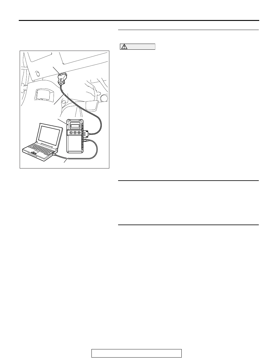
STEP 1. Using scan tool MB991958, diagnose the CAN bus
line.
CAUTION
To prevent damage to scan tool MB991958, always turn the
ignition switch to the "LOCK" (OFF) position before con-
necting or disconnecting scan tool MB991958.
(1) Connect scan tool MB991958. Refer to "How to connect the
Scan Tool (M.U.T.-III)
."
(2) Turn the ignition switch to the "ON" position.
(3) Diagnose the CAN bus line.
(4) Turn the ignition switch to the "LOCK" (OFF) position.
Q: Is the CAN bus line found to be normal?
YES : Go to Step 2.
NO : Repair the CAN bus line (Refer to GROUP 54C,
).
STEP 2. Using scan tool MB991958, read the audio
diagnostic trouble code.
Check if DTC is set to the radio and CD player.
Q: Is the DTC set?
YES : Troubleshoot the audio (Refer to
).
NO : Go to Step 3.
STEP 3. Recheck for diagnostic trouble code.
Check again if the DTC is set to the satellite radio tuner.
(1) Erase the DTC.
(2) Turn the ignition switch from "LOCK" (OFF) position to "ON"
position.
(3) Check if DTC is set.
(4) Turn the ignition switch to the "LOCK" (OFF) position.
Q: Is the DTC set?
YES : Replace the satellite radio tuner.
NO : The trouble can be an intermittent malfunction (Refer
to GROUP 00, How to use
Troubleshooting/inspection Service Points
− How to
Cope with Intermittent Malfunction
AC608435
Data link connector
MB991827
MB991824
MB991910
AB