Mitsubishi Lancer Evolution X. Manual - part 612


  Index      Mitsubishi     Mitsubishi Lancer Evolution X GS41EVO - service repair manual 2008 year


Search            


Content   ..  610  611  612  613   ..


Mitsubishi Lancer Evolution X. Manual - part 612


TRANSMISSION CONTROL

TSB Revision

TWIN CLUTCH- SPORTRONIC SHIFT TRANSMISSION (TC-SST)

22C-405

REMOVAL SERVICE POINT

.

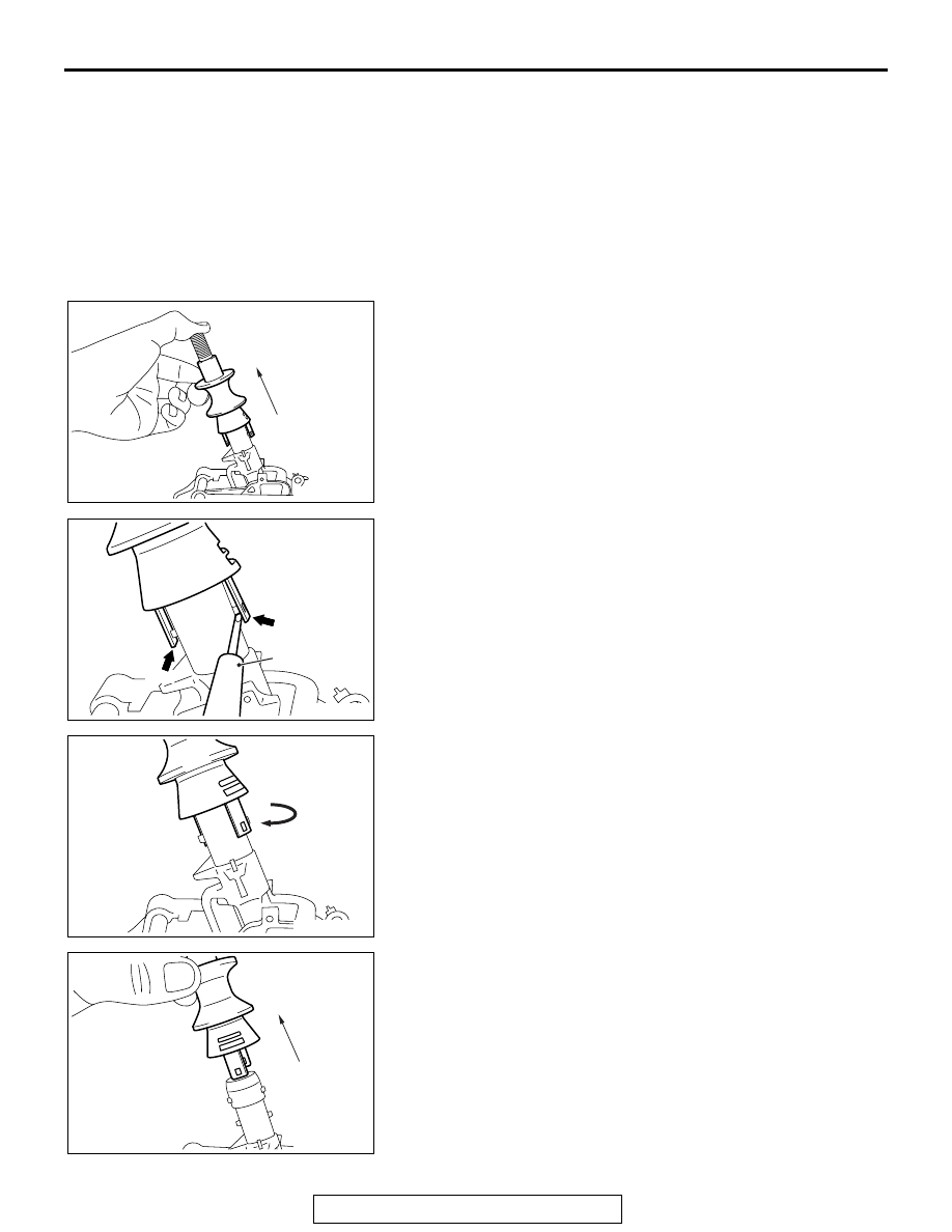
<<A>> PULL RING REMOVAL

1. Pull the pull ring upward as shown in the figure. (Carry out 

the following operation with the pull ring pulled upward.)

2. Raise the claw using a precision screwdriver.

3. Remove the pull ring by turning it clockwise, and pull it out 

upward.

>>

A

<<

8. Transaxle control cable 

connection (transaxle side)

9. Transaxle control cable 

bracket

10. Transaxle control cable

Transaxle control cable 
removal steps (Continued)

AC902247

AD

AC902248

Precision 
screwdriver

Claw

AC

Claw

AC902249

Clockwise

AD

AC902250

AC

TRANSMISSION CONTROL

TSB Revision

TWIN CLUTCH- SPORTRONIC SHIFT TRANSMISSION (TC-SST)

22C-406

INSTALLATION SERVICE POINTS

.

>>A<< TRANSAXLE CONTROL CABLE (TRAN-
SAXLE SIDE/SHIFT LEVER SIDE) INSTALLATION

1. Connect the transaxle control cable (shift lever side) to the 

shift lever assembly.

2. Operate the lever so that the shift control lever positioning 

mark is set to the N position.

3. Move the slider of the transaxle control cable (transaxle 

side) tip to the direction A to pull up the lock piece to the 
direction B.

4. Install the transaxle control cable (transaxle side) in the 

transaxle control cable bracket at the top of transaxle.

5. Move the shift lever to the N⇔D position three times or 

more, and shift to the N position.

6. Connect the transaxle control cable to the shift control lever, 

and firmly push down the lock piece of transaxle control 
cable to lock it.
NOTE: 

.

The slider automatically returns to the fixed position by 
the spring.

The lock position of transaxle control cable is automati-
cally adjusted by a spring.

.

AC707764

P

N
D

AC

Shift control lever

Mark

Shift control lever

AC707742

AD

Shift control
lever

Lock piece

Slider

Transaxle
control cable

A

B

AC707743

AD

Shift control
lever

Lock piece

Slider

Transaxle
control cable

TRANSMISSION CONTROL

TSB Revision

TWIN CLUTCH- SPORTRONIC SHIFT TRANSMISSION (TC-SST)

22C-407

>>B<< KEY INTERLOCK CABLE INSTALLATION

CAUTION

Leave the ignition switch in the LOCK (OFF) position until 
the key interlock cable installation is completed.
1. Move the shift lever to the P position, and turn the ignition 

switch to the LOCK (OFF) position.

2. Install the tip of key interlock cable to the lock cam pin of 

shift lever assembly, using a caution not to twist the inner 
cable.

3. Install the adjuster case with its lock guide pulled up 

(unlocked).

4. With the lock cam pin pushed in the direction B as shown in 

the figure to remove the slack from the key interlock cable, 
securely lower the lock guide and lock it.
NOTE: The lock position of the key interlock cable is auto-
matically adjusted by a spring.

.

>>C<< PULL RING INSTALLATION

1. With the A in the figure raised, install the pull ring by turning 

it counterclockwise.

AC900053

View A

Key inter
lock cable

A

Adjuster case

Inner cable

Lock guide

AC

Spring

Lock

Adjuster case

Lock guide

Unlock

B

Lock cam pin

AC902249

Counterclockwise

AE

Pull ring

A

KEY INTERLOCK AND SHIFT LOCK MECHANISMS

TSB Revision

TWIN CLUTCH- SPORTRONIC SHIFT TRANSMISSION (TC-SST)

22C-408

KEY INTERLOCK AND SHIFT LOCK MECHANISMS

REMOVAL AND INSTALLATION

M1225009800170

Pre-removal Operation
• Floor console bracket (A) and floor console side cover 

removal (Refer to GROUP 52A − Floor Console Assembly 

P.52A-10

.)

• Instrument panel cover lower removal <Leather combina-

tion interior package (Vehicles without side air bag)> 

(Refer to GROUP 52A − Instrument Lower Panel 

P.52A-9

.)

• Steering column lower cover removal (Refer to GROUP 

37 − Steering Shaft 

P.37-33

.)

• Foot duct (driver's side) removal (Refer to GROUP 55 − 

Duct 

P.55-189

.)

Post-installation Operation
• Foot duct (driver's side) installation (Refer to GROUP 55 − 

Duct 

P.55-189

.)

• Steering column lower cover installation (Refer to GROUP 

37 − Steering Shaft 

P.37-33

.)

• Instrument panel cover lower installation <Leather combi-

nation interior package (Vehicles without side air bag)> 

(Refer to GROUP 52A − Instrument Lower Panel 

P.52A-9

.)

• Floor console bracket (A) and floor console side cover 

installation (Refer to GROUP 52A − Floor Console Assem-

bly 

P.52A-10

.)

• Key interlock mechanism check (Refer to 

P.22C-401

.)

• Shift lock mechanism check (Refer to 

P.22C-402

.)

• Shift lever operation check (Refer to 

P.22C-400

.)

AC705527

AC709660AB

2

1

5

3

4

Removal steps 

1.

Band clip

2.

Wiring harness clip

>>

B

<<

3.

Key interlock cable 
connection (shift lever side)

<<

A

>>

>>

A

<<

4.

Key interlock cable 
connection (steering side)

5.

Key interlock cable

Removal steps 


Content   ..  610  611  612  613   ..