Mitsubishi Lancer Evolution X. Manual - part 143
DIAGNOSIS
TSB Revision
ACTIVE STABILITY CONTROL SYSTEM (ASC)
35C-37
STEP 1. Using scan tool MB991958, diagnose the CAN bus
lines.
Using scan tool MB991958, diagnose the CAN bus lines.
Q: Is the check result normal?
YES : Go to Step 3.
NO : Repair the CAN bus lines (Refer to GROUP 54C −
CAN Bus Diagnostics table
). On completion,
go to Step 2.
STEP 2. DTC recheck after repairing the CAN bus line
Q: Is DTC C1020 set?
YES : Go to Step 3.
NO : This diagnosis is complete.
STEP 3. Scan tool service data
Check the following service data. (Refer to
.)
• Item No.03: RL wheel speed sensor
Q: Is the check result normal?
YES : Go to Step 10.
NO : Go to Step 4.
STEP 4. Connector check: Connector check: A-05
ASC-ECU connector, C-45 intermediate connector, D-18
wheel speed sensor <RL> connector
Q: Is the check result normal?
YES : Go to Step 5.
NO : Repair the defective connector. Then go to Step 11.
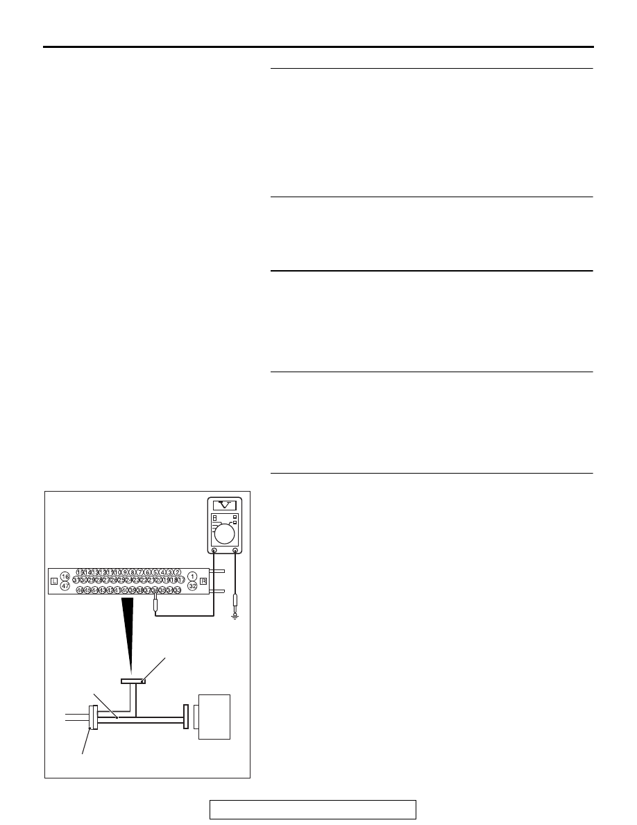
STEP 5. Voltage measurement at A-05 ASC-ECU connector
(1) Disconnect the ASC-ECU connector, connect the special
tool ASC check harness (MB991997) to the wiring
harness-side connector, and then measure at the special
tool connector side.
NOTE: Do not connect the special tool to ASC-ECU.
(2) Turn the ignition switch to the ON position.
(3) Measure the voltage between the wheel speed sensor
power supply terminal (signal terminal) No. 36 and the body
ground as well as between the ground terminal No. 37 and
the body ground.
OK: 1 volt or less
Q: Is the check result normal?
YES : Go to Step 6.
NO (Not normal at the terminal No. 34 or 33) : Go to Step
8.
AC400817CH
ASC-ECU
MB991997
Check harness
A-05 ASC-ECU
harness connector