Mitsubishi Lancer Evolution X. Manual - part 40


  Index      Mitsubishi     Mitsubishi Lancer Evolution X GS41EVO - service repair manual 2008 year


Search            


Content   ..  38  39  40  41   ..


Mitsubishi Lancer Evolution X. Manual - part 40


DIAGNOSIS

TSB Revision

CONTROLLER AREA NETWORK (CAN)

54C-185

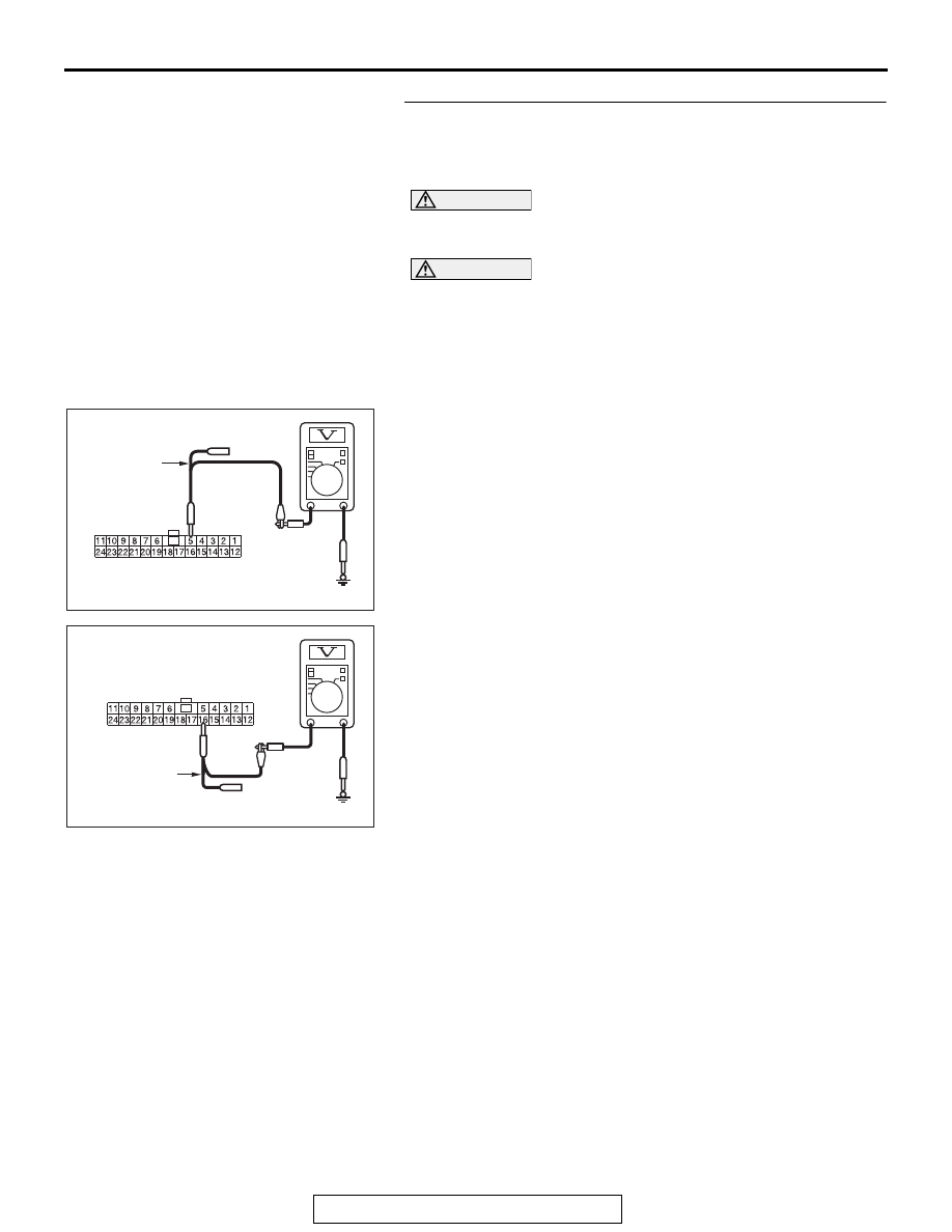
STEP 21. Check the wiring harness between joint 
connector (CAN1) C-105 and CAN box unit connector C-15 
for a short to power supply. Measure the voltage at joint 
connector (CAN1) C-105.

CAUTION

A digital multimeter should be used. For details refer to 

P.54C-7

.

CAUTION

The test wiring harness should be used. For details refer to 

P.54C-7

.

(1) Disconnect joint connector (CAN1), and measure the 

voltage at the wiring harness side of joint connector 
(CAN1).

(2) Turn the ignition switch to the ON position.
(3) Measure the voltage between joint connector (CAN1) 

terminal 5 and body ground.

OK: 4.7 V or less

(4) Measure the voltage between joint connector (CAN1) 

terminal 16 and body ground.

OK: 4.7 V or less

Q: Do all the voltages measure 4.7 V or less?

YES (vehicles without satellite radio) : Go to Step 23.
YES (vehicles with satellite radio) : Go to Step 22.
NO  :  Go to Step 32.

AC608178

TEST 
HARNESS

Harness side: C-105

BV

AC608178

Harness side: C-105

BW

TEST 
HARNESS

DIAGNOSIS

TSB Revision

CONTROLLER AREA NETWORK (CAN)

54C-186

STEP 22. Check the wiring harness between joint 
connector (CAN1) C-105 and satellite radio tuner 
connector C-18 for a short to power supply. Measure the 
voltage at joint connector (CAN1) C-105.

CAUTION

A digital multimeter should be used. For details refer to 

P.54C-7

.

CAUTION

The test wiring harness should be used. For details refer to 

P.54C-7

.

(1) Disconnect joint connector (CAN1), and measure the 

voltage at the wiring harness side of joint connector 
(CAN1).

(2) Turn the ignition switch to the ON position.
(3) Measure the voltage between joint connector (CAN1) 

terminal 2 and body ground.

OK: 4.7 V or less

(4) Measure the voltage between joint connector (CAN1) 

terminal 13 and body ground.

OK: 4.7 V or less

Q: Do all the voltages measure 4.7 V or less?

YES : Go to Step 23.
NO :  Go to Step 33.

AC608178

TEST 
HARNESS

Harness side: C-105

BY

AC608178

Harness side: C-06

BE

TEST 
HARNESS

DIAGNOSIS

TSB Revision

CONTROLLER AREA NETWORK (CAN)

54C-187

STEP 23. Check the wiring harness between joint 
connector (CAN1) C-105 and ETACS-ECU connector C-301 
for a short to power supply. Measure the voltage at joint 
connector (CAN1) C-105.

CAUTION

A digital multimeter should be used. For details refer to 

P.54C-7

.

CAUTION

The test wiring harness should be used. For details refer to 

P.54C-7

.

(1) Disconnect joint connector (CAN1) and ETACS-ECU 

connector C-301, and measure the voltage at the wiring 
harness side of joint connector (CAN1).

(2) Turn the ignition switch to the ON position.
(3) Measure the voltage between joint connector (CAN1) 

terminal 6 and body ground.

OK: 1 V or less

(4) Measure the voltage between joint connector (CAN1) 

terminal 19 and body ground.

OK: 1 V or less

Q: Do all the voltages measure 1 V or less?

YES : Go to Step 34.
NO :  Repair the wiring harness between joint connector 

(CAN1) C-105 and ETACS-ECU connector C-301.

AC608178

TEST 
HARNESS

Harness side: C-105

BX

AC608178

Harness side: C-105

BZ

TEST 
HARNESS

DIAGNOSIS

TSB Revision

CONTROLLER AREA NETWORK (CAN)

54C-188

STEP 24. Using scan tool MB991958, diagnose the CAN 
bus line. (checking the combination meter for internal 
failure)

CAUTION

Strictly observe the specified wiring harness repair proce-
dure. For details refer to 

P.54C-7

.

CAUTION

To prevent damage to scan tool MB991958, always turn the 
ignition switch to the "LOCK" (OFF) position before con-
necting or disconnecting scan tool MB991958.
(1) Disconnect combination meter connector C-04.
(2) Connect scan tool MB991958 to the data link connector.
(3) Turn the ignition switch to the "ON" position.

AC608435

Data link connector

MB991827

MB991824

MB991910

AB


Content   ..  38  39  40  41   ..