Mitsubishi Lancer Evolution IX. Manual - part 655
 

  Index      Mitsubishi     Mitsubishi Lancer Evolution IX - service repair manual


Search            


Content   ..  653  654  655  656   ..


Mitsubishi Lancer Evolution IX. Manual - part 655


Wire colour code
B : Black     LG : Light green     G : Green     L : Blue     W : White     Y : Yellow     SB : Sky blue
BR : Brown     O : Orange     GR : Grey     R : Red     P : Pink     V : Violet     PU : Purple

INPUT SIGNAL

· A/C SWITCH
· ENGINE
  COOLANT
  TEMPERATURE
  SENSOR

· VEHICLE SPEED
  SENSOR

ENGINE-
ECU

ENGINE
CONTROL
RELAY

SMOOTHING
CIRCUIT

FIELD EFFECT
TRANSISTOR
CIRCUIT

INPUT SIGNAL
PROCESSING

DRIVE
CIRCUIT

TEMPERATURE
DETECTION

CURRENT
DETECTION

RADIATOR
FAN
MOTOR

FAN CONTROLLER

ENGINE
CONTROL
SYSTEM

FUSIBLE
LINK

2

FAN
CONTROL
RELAY

AC505139

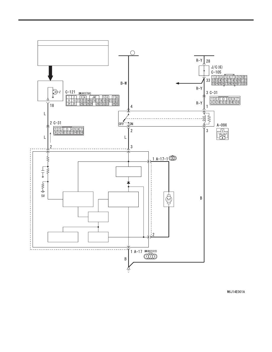
Cooling fan drive circuit <R.H. drive vehicles>

AB

TROUBLESHOOTING

ENGINE COOLING

14-5

CIRCUIT OPERATION

• The fan controller is powered from fusible link 

No.2.

• The engine-ECU judges the required revolution 

speed of cooling fan motor using the input signals 
transmitted from A/C switch, vehicle speed sen-
sor and engine coolant temperature sensor. The 
engine-ECU activates the fan controller to drive 
the cooling fan motor.

TROUBLESHOOTING

ENGINE COOLING

14-6

TECHNICAL DESCRIPTION

• The cause could be a malfunction of the fan con-

troller power supply or earth circuit.

• The cause could also be a malfunction of the fan 

controller or the engine-ECU.

TROUBLESHOOTING HINTS

• Malfunction of fusible link

• Malfunction of fan control relay

• Malfunction of cooling fan motor

• Malfunction of fan controller

• Malfunction of engine-ECU

• Damaged wiring harness or connector

DIAGNOSIS

STEP 1. Check the circuit at fan controller 
connector A-17 terminal 3.

AC210859

Connector: A-17

A-17 (GR)

AD

Fan controller

Component side

(1) Disconnect fan controller connector A-17, and 

measure at the harness side connector.

(2) Measure the voltage between terminal No.3 and 

earth.

• When the ignition switch is turned to the "ON" 

position, voltage should measure battery pos-
itive voltage.

Q: Is the voltage battery positive voltage when the 

ignition switch is turned to the "ON" position?
YES : 

Go to Step 7.

NO : 

Go to Step 2.

STEP 2. Check the fan control relay.
 Refer to 

P.14-17

.

Q: Is the fan control relay in good condition?

YES : 

Go to Step 3.

NO : 

Replace it, then go to Step 1.

STEP 3. Check for harness damage between 
fusible link No.2 and fan control relay connector 
A-09X terminal 4.

AC310900AC

Fusible link (2)

Fusible link (2) And
Connector: A-09X

A-09X

3

1

4

2

Relay box 
side

Q: Are the harness wires between fusible link No.2 

and fan control relay connector A-09X damaged? 
YES : 

Repair or replace them, then go to Step 13.

NO : 

Go to Step 4.

STEP 4. Check for harness damage between fan 
control relay connector A-09X terminal 2 and fan 
controller connector A-17 terminal 3.

AC310900AB

Connector: A-09X

A-09X

3

1

4

2

Relay box 
side

AC210859

Connector: A-17

A-17 (GR)

AD

Fan controller

Component side

Q: Are the harness wires between fan control relay 

connector A-09X terminal 2 and fan controller 
connector A-17 terminal 3 damaged?
YES : 

Repair or replace them, then go to Step 13.

NO : 

Go to Step 5.

TROUBLESHOOTING

ENGINE COOLING

14-7

STEP 5. Check for harness damage between J/C 
(6) C-105 and fan control relay connector A-09X.
NOTE: 

AC210877AC

Connector: A-13 <LHD>

A-13 (B)

AC310903AB

Connector: C-31 <RHD>

C-31

AC310901AB

Connector: C-105 <LHD>

C-105

AC310902AB

Connector: C-105 <RHD>

C-105

After inspecting intermediate connector A-13 <LHD> 
terminal 3, intermediate connector C-31 <RHD> ter-
minal 12 and J/C (6) C-105 terminal 28, 33 inspect 
the wires. If intermediate connector A-13 <LHD>, 
C-31<RHD> and J/C (6) C-105 are damaged, repair 
or replace them. Refer to GROUP 00, How to Use 
Troubleshooting/Inspection Service Points 

P.00-5

.

AC310900AB

Connector: A-09X

A-09X

3

1

4

2

Relay box 
side

AC310901AB

Connector: C-105 <LHD>

C-105

AC310902AB

Connector: C-105 <RHD>

C-105

Q: Are the harness wires between J/C (6) C-105 

terminal 28 and fan control relay connector A-09X 
terminal 1 damaged?
YES : 

Repair or replace them, then go to Step 13.

NO : 

Go to Step 6.

STEP 6. Check for harness damage between fan 
control relay connector A-09X terminal 3 and 
earth.

AC310900AB

Connector: A-09X

A-09X

3

1

4

2

Relay box 
side

TROUBLESHOOTING

ENGINE COOLING

14-8

Q: Are the harness wires between fan control relay 

connector A-09X terminal 3 and earth damaged?
YES : 

Repair or replace them, then go to Step 13.

NO : 

Go to Step 7.

STEP 7. Check the cooling fan motor.
 Refer to 

P.14-17

.

Q: Is the cooling fan motor in good condition?

YES : 

Go to Step 8.

NO : 

Replace it, then go to Step 13.

STEP 8. Check the circuit at fan controller 
connector A-17 terminal 1.

AC210859

Connector: A-17

A-17 (GR)

AD

Fan controller

Component side

(1) Disconnect fan controller connector A-17, and 

measure at the harness side connector.

(2) Measure the resistance between terminal No.1 

and earth.

• The resistance should measure less than 2 

ohms.

Q: Is the resistance less than 2 ohms?

YES : 

Go to Step 10.

NO : 

Go to Step 9.

STEP 9. Check the harness wire between fan 
controller connector A-17 and earth.

AC210859

Connector: A-17

A-17 (GR)

AD

Fan controller

Component side

Q: Are the harness wires between fan controller 

connector A-17 and earth damaged?
YES : 

Repair or replace them, then go to Step 13.

NO : 

Go to Step 10.

STEP 10. Measure the output circuit voltage at 
engine-ECU connector C-121 terminal 18 by 
backprobing.

AC505254

16

25

10

24

1
9

2

4

27

13

26

11

3

12

2829

1415

3031

1718

33

32

6

20

5

19

21

35

34

8

23

7

22

JAE

AB

Connector: C-121 <LHD>

Harness side

C-121 (GR)

Engine-ECU

AC505255

16

25

10

24

1
9

2

4

27

13

26

11

3

12

2829

1415

3031

1718

33

32

6

20

5

19

21

35

34

8

23

7

22

JAE

AB

Connector: C-121 <RHD>

Harness side

C-121 (GR)

Engine-ECU

(1) Do not disconnect engine-ECU connector C-121.
(2) Start the engine and allow it to idle.
(3) Turn the A/C switch to the "ON" position.
(4) Measure the voltage between terminal No.18 and 

earth by backprobing.

• The voltage should measure 0.7 volt or more 

when the cooling fan is operating.

Q: Is the voltage 0.7 volt or more when the cooling fan 

is operating?
YES : 

Go to Step 12.

NO : 

Go to Step 11.


Content   ..  653  654  655  656   ..