Mitsubishi Lancer Evolution IX. Manual - part 650
 

  Index      Mitsubishi     Mitsubishi Lancer Evolution IX - service repair manual


Search            


Content   ..  648  649  650  651   ..


Mitsubishi Lancer Evolution IX. Manual - part 650


DRIVER'S AND PASSENGER'S (FRONT) AIR BAG MODULES AND CLOCK SPRING

SUPPLEMENTAL RESTRAINT SYSTEM (SRS)

52B-113

<<B>> STEERING WHEEL AND DRIVER’S 
AIR BAG MODULE ASSEMBLY REMOVAL

WARNING

The air bag module must not be measured 
with such equipment as an ohmmeter, nor 
disassembled.

The removed air bag module should be 
stored in a clean, dry place with the 
deployment surface facing up.

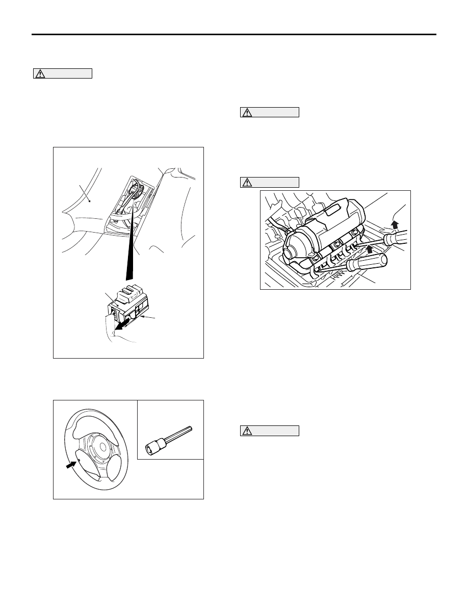
1. By sliding the A section (in the figure) of the air 

bag module connector in the arrow direction, 
disconnect the connector.

2. Insert the hexagonal bit socket into the arrow 

section in the figure. Completely loosen the bolt, 
and then remove the steering wheel air bag 
module assembly.

NOTE: Use a hexagonal bit socket or a hexagonal 
wrench having an effective length of 75 mm or 
more in the hexagonal section and the diameter of 
8 mm or more.

<C>> CLOCK SPRING REMOVAL

WARNING

The removed clock spring should be stored 
in a clean, dry place.

<<D>> PASSENGER’S (FRONT) AIR BAG 
MODULE REMOVAL 

WARNING

When the air bag module is removed, do not 

damage the engagement of the pawls.

The removed air bag module should be 
stored in a clean, dry place with facing the 
deployment surface facing up.

Insert the screwdriver (

−) into the position specified 

in the figure and lift the screwdriver upward to 
release the pawls engaged, and then remove the air 
bag module.

INSTALLATION SERVICE POINTS
>>A<< PRE-INSTALLATION INSPECTION

WARNING

Dispose of air bag modules only according 
to the specified procedure (Refer to 

P.52B-120

).

1. When installing the new air bag modules and 

clock spring, refer to “INSPECTION” (

P.52B-115

).

2. Connect the negative battery cable.

AC105823

AC304700

AC305145AB

A

Steering
wheel

Air bag module 
connector

AC211762 AC

Hexagonal bit
socket

AC100443

DRIVER'S AND PASSENGER'S (FRONT) AIR BAG MODULES AND CLOCK SPRING

SUPPLEMENTAL RESTRAINT SYSTEM (SRS)

52B-114

CAUTION

To prevent damage to M.U.T.-II/III, always turn the 
ignition, switch to the “LOCK” (OFF) position 
before connecting or disconnecting M.U.T.-II/III.
3. Connect M.U.T.-II/III to the diagnosis connector.
4. Turn the ignition switch to the “ON” position.
5. Check diagnosis codes using M.U.T.-II/III ensure 

that the SRS operates properly.
Confirm that the diagnosis codes other than 21 
and 24 are not set.

DANGER

Wait at least 60 seconds after disconnecting 
the battery cable before doing any further 
work (Refer to 

P.52B-3

).

6. Turn the ignition switch to the "LOCK" (OFF) 

position. Disconnect the negative battery cable 
and tape the terminal to prevent accidental 
connection and air bags deployment.

>>B<< CLOCK SPRING INSTALLATION

WARNING

Ensure that the clock spring’s mating marks 
are properly aligned. If not, the steering 
wheel may not rotate completely during a 
turn, or the flat cable in the clock spring 
could be damaged, This would prevent nor-
mal SRS operation and possibly cause seri-
ous injury to the driver.

1. Align the mating marks of the clock spring. 

<Mating Mark Alignment>
Turn the clock spring clockwise fully. Then turn it 
back approximately 3 3/4 turns counterclockwise 
to align the mating marks.

2. Turn the front wheels to the straight-ahead 

position. Then install the clock spring to the 
column switch.

>>C<< STEERING WHEEL AND DRIVER’S 
AIR BAG MODULE ASSEMBLY 
INSTALLATION

CAUTION

When installing the steering wheel, and driver’s 
air bag module ensure that the harness of the 
clock spring does not become caught or tangled.
1. Before installing the steering wheel, and driver’s 

air bag module turn the vehicle’s front wheels to 
the straight-ahead position and align the mating 
marks of the clock spring.

2. After securing the steering wheel, turn the 

steering wheel all the way in both directions to 
confirm that the steering wheel rotation is normal.

>>D<< POST-INSTALLATION 
INSPECTION

1. Reconnect the negative battery cable.
2. Turn the ignition switch to “ON” position.

AC304777

Steering shaft

AB

MB991502

<Using the M.U.T.-II>

AC211686

MB991911

16-PIN

MB991827

MB991824 

AE

<Using the M.U.T.-III>

AC300168

Mating marks

AB

DRIVER'S AND PASSENGER'S (FRONT) AIR BAG MODULES AND CLOCK SPRING

SUPPLEMENTAL RESTRAINT SYSTEM (SRS)

52B-115

3. Does the SRS warning lamp illuminate for about 7 

seconds and then goes out?

4. If yes, the SRS system is functioning properly. If 

no, refer to 

P.52B-8

.

INSPECTION

M1524014600039

AIR BAG MODULE CHECK

WARNING

If any component damage is found during 
the following inspection, replace the air 
bag module(s) with a new one. Dispose of 
the old one according to the specified 
procedure (Refer to 

P.52B-120

).

Never attempt to measure the circuit 
resistance of he air bag module (squib) 
even if you are using the specified tester. 
If the circuit resistance is measured with a 
tester, accidental air bag module(s) 
deployment will result in serious personal 
injury.

1. Check the pad cover for dents, cracks or 

deformation.

2. Check the connectors for damage, the terminals 

for deformation, and the harness for binds.

3. Check the air bag inflator case for dents, cracks or 

deformation.

4. Install the air bag module (driver’s side) to the 

steering wheel and check fit and alignment with 
the wheel. 

5. Install the air bag module (front passenger’s side) 

to the instrument panel and front deck 
crossmember and check fit and alignment.

AC311044

SRS warning lamp

AB

AC006205

AC311067

AC304700

Steering 
wheel

AC

Inflator case

Connector

<Driver's side>

Connector

<Front passenger's side>

DRIVER'S AND PASSENGER'S (FRONT) AIR BAG MODULES AND CLOCK SPRING

SUPPLEMENTAL RESTRAINT SYSTEM (SRS)

52B-116

CLOCK SPRING CHECK

If any malfunction is found in the following inspec-
tions, replace the clock spring with a new one.
1. Check the connectors and protective tube for 

damage, and the terminals for deformation.

2. Visually check the case for damage.
3. Check to see that there is a charge (continuity) 

between the C-204 clock spring connector 
terminal 1 and C-203 horn switch.

CAUTION

 Do not directly insert a probe, etc. into the termi-
nal from the front of the connector.
4.  Insert the special tool extra fine probe 

(MB992006) from behind the C-205 air bag 
module connector (driver’s side).

5.  As shown in the Figure, connect the circuit tester 

to the special tool extra fine probe (MB992006) 
and check to see that there is a charge between 
the terminals.

5 6

1 2 3 4

AC300312AD

Case

C-204 Clock spring
connector

Protective tube

C-205 Air bag
module connector

C-203 Horn switch

AC300374AE

Clock spring

C-205 Air bag
module connector
(driver's side)

C-205 Air bag
module connector

Extra fine probe
(MB992006)

Digital
multi-meter


Content   ..  648  649  650  651   ..