Mitsubishi Lancer Evolution IX. Manual - part 614
 

  Index      Mitsubishi     Mitsubishi Lancer Evolution IX - service repair manual


Search            


Content   ..  612  613  614  615   ..


Mitsubishi Lancer Evolution IX. Manual - part 614


TROUBLESHOOTING <ACD>

MANUAL TRANSMISSION (FF)

22A-139

STEP 2. Connectors check: C-01 combination 
meter connector, C-26 4WD-ECU connector, 
C-122 intermediate connector <LH drive 
vehicles> or C-01 combination meter connector, 
C-26 4WD-ECU connector, C-138 intermediate 
connector <RH drive vehicles>.

Check for the contact with terminals.

Q: Is the check result normal?

YES : 

Go to Step 3.

NO : 

Repair the defective connector.

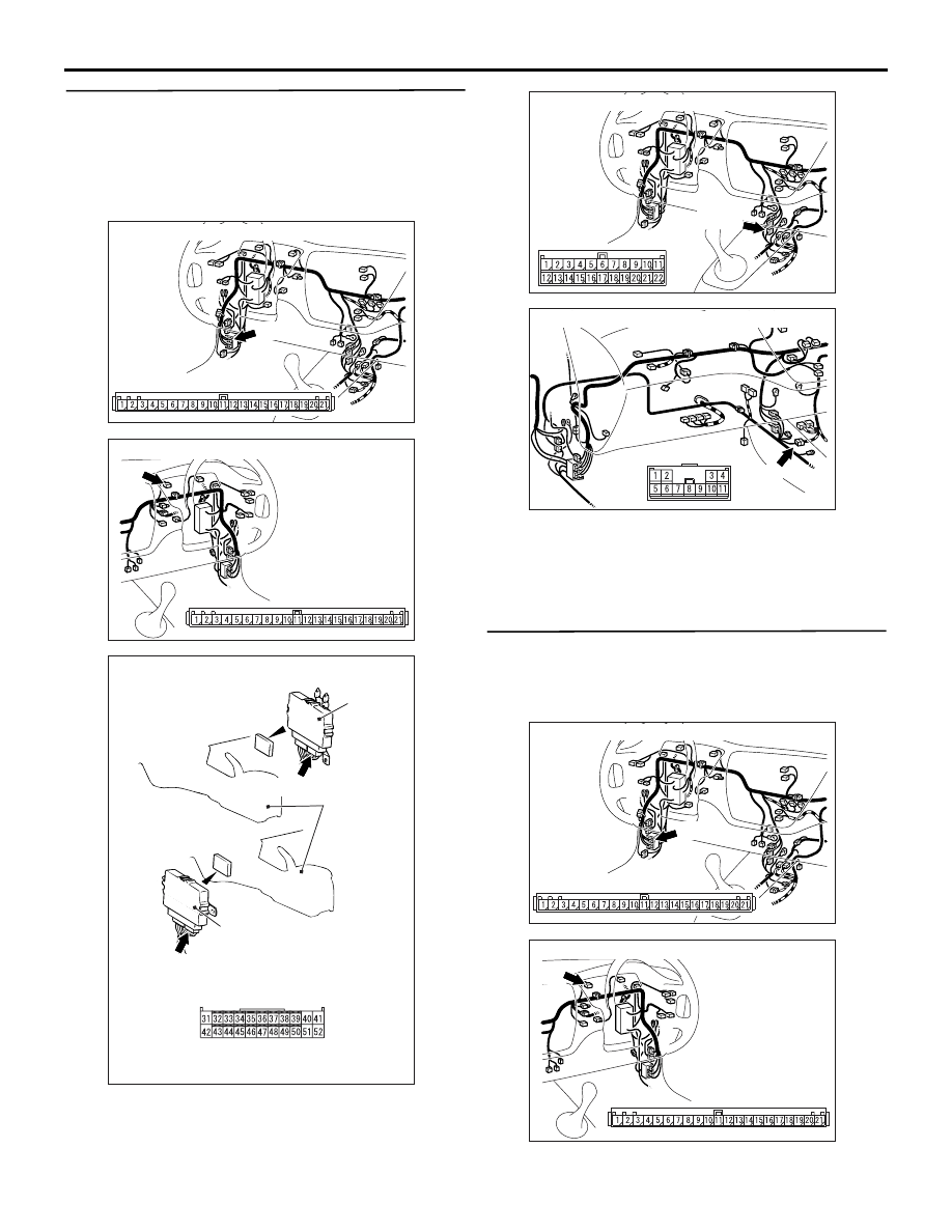
STEP 3. Check the harness between combination 
meter connector C-01 (terminal No.10, 14, 15) and 
4WD-ECU connector C-26 (terminal No.40, 52, 
51).

AC311015AO

Connector: C-01 <LH drive vehicles>

C-01

C-01

AC311037

C-01

AG

Connector: C-01 <RH drive vehicles>

C-01

AC311002

4WD-ECU

Harness side

C-26 (Y)

AC

Connector: C-26

4WD-ECU

C-26 (Y)

Rear console 
assembly

<LH drive vehicles>

<RH drive vehicles>

AC311015AC

Connector: C-122 <LH drive vehicles>

C-122

AC311016AB

Connector: C-138 <RH drive vehicles>

C-138

AC311015AO

Connector: C-01 <LH drive vehicles>

C-01

C-01

AC311037

C-01

AG

Connector: C-01 <RH drive vehicles>

C-01

TROUBLESHOOTING <ACD>

MANUAL TRANSMISSION (FF)

22A-140

Check the output line for short or open circuit.

Q: Is the check result normal?

YES : 

Replace the ACD mode indicator lamp 

assembly.

NO : 

Repair the wiring harness.

AC311002

4WD-ECU

Harness side

C-26 (Y)

AC

Connector: C-26

4WD-ECU

C-26 (Y)

Rear console 
assembly

<LH drive vehicles>

<RH drive vehicles>

TROUBLESHOOTING <ACD>

MANUAL TRANSMISSION (FF)

22A-141

INSPECTION PROCEDURE 5: The ACD does not operate (no diagnosis code)

COMMENTS ON TROUBLE SYMPTOM

Insufficient operating oil, oil leakage, faulty opera-
tions of the oil pressure unit, and faulty operations of 
the ACD transfer may be suspected.

PROBABLE CAUSES

• Leakage of transfer oil

• Insufficient transfer oil

• Leakage of oil pressure line

• Insufficient fluid

• Malfunction of the hydraulic unit

• Malfunction of the ACD transfer

DIAGNOSIS

STEP 1. Check the transfer oil.
Refer to 

P.22A-152

.

Q: Is the check result normal?

YES : 

Go to Step 3.

NO : 

Go to Step 2.

STEP 2. Check the transfer oil leaks.
Check that the transfer oil is not leaking.

Q: Is the check result normal?

YES : 

Add the transfer oil.

NO : 

Repair the leaking part and add the transfer 
oil.

STEP 3. Check the fluid.
Refer to 

P.22A-152

.

Q: Is the check result normal?

YES : 

Go to Step 5.

NO : 

Go to Step 4.

STEP 4. Check the fluid leaks.
Check that the fluid is not leaking.

Q: Is the check result normal?

YES : 

Add the fluid.

NO : 

Repair the leaking part and add the fluid.

STEP 5. Check the ACD operation.
Refer to 

P.22A-153

.

Q: Is the check result normal?

YES : 

The inspection is complete.

NO : 

Go to Step 6.

STEP 6. Check the fluid pressure.
Refer to 

P.22A-154

.

Q: Is the check result normal?

YES : 

Go to Step 7.

NO : 

Go to Step 8.

STEP 7. Check the hydraulic pressure line.
Check that the hydraulic pressure line is not contam-
inated with foreign materials.

Q: Is the check result normal?

YES : 

Replace the ACD transfer.

NO : 

Repair.

STEP 8. Perform air bleeding.
Refer to 

P.22A-153

.

Q: Is the check result normal?

YES : 

The procedure is complete.

NO : 

Replace the hydraulic pressure unit.

TROUBLESHOOTING <ACD>

MANUAL TRANSMISSION (FF)

22A-142

DATA LIST REFERENCE TABLE

M1221011200010

Item 
No.

Check item

Check condition

Normal 
condition

01

Wheel speed sensor 
<FR>

Execute actual driving.

The speed meter 
display and 
M.U.T.-II/III 
display match.

02

Wheel speed sensor 
<FL>

03

Wheel speed sensor 
<RR>

04

Wheel speed sensor 
<RL>

05

Wheel speed sensor 
<FR> (0.2 km/h)

06

Wheel speed sensor 
<FL> (0.2 km/h)

07

Wheel speed sensor 
<RR> (0.2 km/h)

08

Wheel speed sensor 
<RL> (0.2 km/h)

09

Vehicle speed

10

Battery voltage

Ignition switch: ON

System voltage

11

Proportional valve 
current <ACD>

During ACD operation

50 

− 1,000 mA

12

Proportional valve 
current <AYC>

During AYC operation

50 

− 1,000 mA

13

TPS voltage

• Ignition switch: ON

• Engine: Stopped

Accelerator pedal: Full 
closed

535 

− 735 mV

Accelerator pedal: Press

Gradually rises 
from the above 
value

Accelerator pedal: Full 
throttle

4,500 

− 5,000 

mV

14

Longitudinal G-sensor 
voltage

Ignition switch: ON

Vehicle stopped (horizontal) 
state

2.4 

− 2.6 V

Actual driving

The displayed 
value increases 
and decreases 
mainly around 
2.5 V.

15

Lateral G-sensor 
voltage

Ignition switch: ON

Vehicle stopped (horizontal) 
state

2.4 

− 2.6 V

Perform actual driving

The displayed 
value increases 
and decreases 
mainly around 
2.5 V.


Content   ..  612  613  614  615   ..