Mitsubishi Lancer Evolution IX. Manual - part 610
 

  Index      Mitsubishi     Mitsubishi Lancer Evolution IX - service repair manual


Search            


Content   ..  608  609  610  611   ..


Mitsubishi Lancer Evolution IX. Manual - part 610


TROUBLESHOOTING <ACD>

MANUAL TRANSMISSION (FF)

22A-123

STEP 4. Measure the resistance at diagnosis 
connector C-14.

Measure the resistance between terminal No.4, No.5 
and earth.

OK: 2 

 or less

Q: Is the check result normal?

YES : 

Replace the M.U.T.-II/III.

NO : 

Go to Step 5.

STEP 5. Connector check: C-14 diagnosis 
connector.

Check for the contact with terminals.

Q: Is the check result normal?

YES : 

Go to Step 6.

NO : 

Repair the defective connector.

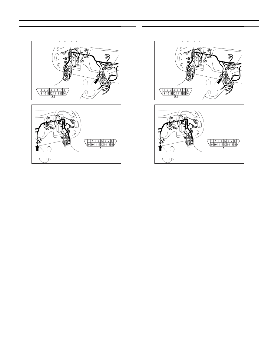
AC311015AM

Connector: C-14 <LH drive vehicles>

C-14 (B)

C-14

AC311037

C-14 (B)

AE

Connector: C-14 <RH drive vehicles>

C-14

AC311015AM

Connector: C-14 <LH drive vehicles>

C-14 (B)

C-14

AC311037

C-14 (B)

AE

Connector: C-14 <RH drive vehicles>

C-14

TROUBLESHOOTING <ACD>

MANUAL TRANSMISSION (FF)

22A-124

STEP 6. Check the harness between diagnosis 
connector C-14 terminal No.4, No.5 and earth.

Check the earth line for open circuit.

Q: Is the check result normal?

YES : 

Intermittent malfunction (Refer to GROUP 

00 

− How to Cope with Intermittent 

Malfunction 

P.00-5

).

NO : 

Repair the wiring harness.

INSPECTION PROCEDURE 2: No Communication possible between M.U.T.-II/III and 4WD-ECU

DIAGNOSIS CONNECTOR CIRCUIT

Refer to 

P.22A-119

.

OPERATION

The M.U.T.-II/III will be able to communicate with the 
4WD-ECU by connecting the diagnosis connector.

COMMENTS ON TROUBLE SYMPTOM

The diagnostic output circuit, 4WD-ECU power sup-
ply circuit, earth circuit, or 4WD-ECU may be faulty.

PROBABLE CAUSES

• Damaged harness wires and connectors

• Malfunction of the 4WD-ECU

AC311015AM

Connector: C-14 <LH drive vehicles>

C-14 (B)

C-14

AC311037

C-14 (B)

AE

Connector: C-14 <RH drive vehicles>

C-14

TROUBLESHOOTING <ACD>

MANUAL TRANSMISSION (FF)

22A-125

DIAGNOSIS

STEP 1. Measure the harness resistance between 
diagnosis connector C-14 and 4WD-ECU 
connector C-26.

Measure the resistance between connector C-14 ter-

minal No.1 and connector C-26 terminal No.46.

• Measure the resistance between connector C-14 

terminal No.7 and connector C-26 terminal 
No.35.

OK: 2 

 or less

Q: Is the check result normal?

YES : 

Go to Step 4.

NO : 

Go to Step 2.

AC311015AM

Connector: C-14 <LH drive vehicles>

C-14 (B)

C-14

AC311037

C-14 (B)

AE

Connector: C-14 <RH drive vehicles>

C-14

AC311002

4WD-ECU

Harness side

C-26 (Y)

AC

Connector: C-26

4WD-ECU

C-26 (Y)

Rear console 
assembly

<LH drive vehicles>

<RH drive vehicles>

TROUBLESHOOTING <ACD>

MANUAL TRANSMISSION (FF)

22A-126

STEP 2. Connectors check: C-14 diagnosis 
connector, C-23 J/C (4), C-26 4WD-ECU 
connector, C-101 J/C (2), C-105 J/C (6), C-124 
intermediate connector <LH drive vehicles> or 
C-14 diagnosis connector, C-21 J/C (5), C-23 J/C 
(4), C-26 4WD-ECU connector, C-105 J/C (6), 
C-122, C-124 intermediate connector <RH drive 
vehicles>.

Check for the contact with terminals.

Q: Is the check result normal?

YES : 

Go to Step 3.

NO : 

Repair the defective connector.

AC311087

Connector: C-14, C-23, C-101, C-105, C-124 
<LH drive vehicles>

AB

C-14

C-23, C-101

C-105

C-124

C-14 (B)

C-23 (B)

C-101 (L)

C-105

C-124

AC311088

Connector: C-14, 23 <RH drive vehicles>

AB

C-14

C-23

C-14 (B)

C-23 (B)

AC311089

Connector: C-21, C-105, C-122, C-124 
<RH drive vehicles>

AB

C-21

C-105

C-122

C-124

C-21

C-105

C-122 (L)

C-124

AC311002

4WD-ECU

Harness side

C-26 (Y)

AC

Connector: C-26

4WD-ECU

C-26 (Y)

Rear console 
assembly

<LH drive vehicles>

<RH drive vehicles>


Content   ..  608  609  610  611   ..