Mitsubishi Lancer Evolution IX. Manual - part 597
TROUBLESHOOTING <ACD>
MANUAL TRANSMISSION (FF)
22A-71
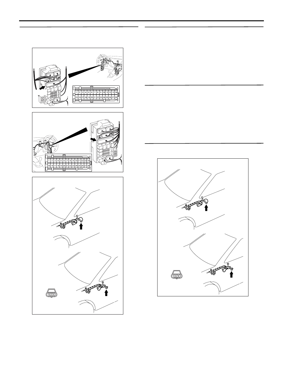
STEP 4. Check the harness between J/B
connector C-214 terminal No.26 and lateral
G-sensor connector D-37 terminal No.1.
Check the power supply line for short or open circuit.
Q: Is the check result normal?
YES :
Go to Step 5.
NO :
Repair the wiring harness.
STEP 5. Replace the lateral G-sensor and then
recheck the diagnosis code.
(1) Replace the lateral G-sensor.
(2) Test drive the vehicle.
(3) Check the diagnosis code.
Q: Is the diagnosis code set?
YES :
Go to Step 6.
NO :
The inspection is complete.
STEP 6. M.U.T.-II/III data list
Item 15: Lateral G-sensor voltage (Refer to data list
reference table
Q: Is the check result normal?
YES :
Intermittent malfunction (Refer to GROUP
00
− How to Cope with Intermittent
).
NO :
Replace the 4WD-ECU.
STEP 7. Measure the resistance at lateral
G-sensor connector D-37.
Disconnect the lateral G-sensor connector, and
measure the resistance between terminal No.3 and
earth.
OK: 2
Ω or less
Q: Is the check result normal?
YES :
Go to Step 12.
NO :
Go to Step 8.
AC310448
AU
Connector: C-214 <LH drive vehicles>
Junction block (front view)
Junction block side
C-214
AC310458
AO
Connector: C-214
<RH drive vehicles>
Junction block (front view)
Junction
block side
C-214
AC311048
<LH drive vehicles>
Sensor side
D-37 (B)
AC
Connector: D-37
<RH drive vehicles>
D-37 (B)
AC311048
<LH drive vehicles>
Sensor side
D-37 (B)
AC
Connector: D-37
<RH drive vehicles>
D-37 (B)