Mitsubishi Lancer Evolution IX. Manual - part 551
 

  Index      Mitsubishi     Mitsubishi Lancer Evolution IX - service repair manual


Search            


Content   ..  549  550  551  552   ..


Mitsubishi Lancer Evolution IX. Manual - part 551


TROUBLESHOOTING

HEATER, AIR CONDITIONER AND VENTILATION

55-77

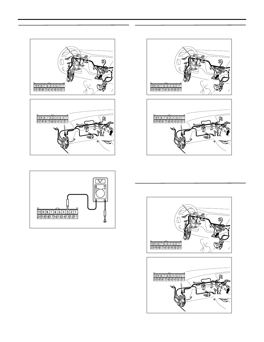
STEP 7. Voltage measurement at C-36 A/C-ECU 
connector. 

(1) Disconnect the connector, and measure at the 

wiring harness side.

(2) Measure the voltage between terminal 3 and 

earth.

OK: System voltage

Q: Is the check result normal?

YES : 

Replace the automatic A/C control panel 

(A/C-ECU).

NO : 

 Go to Step 8.

STEP 8. Connector check: C-36 A/C-ECU 
connector

Q:  Is the check result normal?

YES : 

Go to Step 9.

NO : 

Repair the connector.

STEP 9. Check the wiring harness between C-36 
A/C-ECU connector terminal No.3 and battery.

AC504622AB

Connector: C-36 <LHD>

Harness side

C-36 (B)

AC504618AJ

Connector: C-36 <RHD>

Harness side

C-36 (B)

AC301541JX

Connector C-36
(Harness side)

AC504622AB

Connector: C-36 <LHD>

Harness side

C-36 (B)

AC504618AJ

Connector: C-36 <RHD>

Harness side

C-36 (B)

AC504622AB

Connector: C-36 <LHD>

Harness side

C-36 (B)

AC504618AJ

Connector: C-36 <RHD>

Harness side

C-36 (B)

TROUBLESHOOTING

HEATER, AIR CONDITIONER AND VENTILATION

55-78

NOTE: 

Prior to the wiring harness inspection, check interme-
diate connector C-129 and joint connector C-05, and 
repair if necessary.

• Check the A/C-ECU power supply (battery 

back-up) line for open or short circuit.

Q: Is the check result normal?

YES : 

The trouble can be an intermittent 

malfunction (Refer to GROUP 00, How to 

Cope with Intermittent Malfunction 

P.00-5

).

NO : 

Repair the wiring harness.

AC504641AB

Connectors: C-05, C-129 <LHD>

C-129

C-129

C-05

C-05 (GR)

AC504624AD

Connectors: C-05, C-129 <RHD>

C-05

C-129

C-129

C-05 (GR)

TROUBLESHOOTING

HEATER, AIR CONDITIONER AND VENTILATION

55-79

Inspection Procedure 10: A/C Compressor power supply system.

COMMENTS ON TROUBLE SYMPTOM

If the power is not supplied to the A/C compressor, 
the A/C compressor circuit system may be defective.

POSSIBLE CAUSES

• Malfunction of the A/C compressor relay

• Damaged the wiring harness or connectors

A/C Compressor Circuit

Wire colour code
B : Black     LG : Light green     G : Green     L : Blue    W : White    
Y : Yellow     SB : Sky blue     BR : Brown    O : Orange     
GR : Grey     R : Red     P : Pink     V : Violet    PU : Purple

A/C 
COMPRESSOR 
RELAY

A/C
COMPRESSOR

A/C
REFRIGERANT
TEMPERATURE
SWITCH

MAGNETIC
CLUTCH

IGNITION
SWITCH (IG2)   

ENGINE-ECU

BATTERY

RELAY 
BOX

TROUBLESHOOTING

HEATER, AIR CONDITIONER AND VENTILATION

55-80

DIAGNOSIS PROCEDURE

STEP 1. Connector check: B-13X A/C 
compressor relay connector

Q:  Is the check result normal?

YES : 

Go to Step 2.

NO : 

Repair the connector.

STEP 2. Check the A/C compressor relay 
continuity.
Refer to 

P.55-107

.

Q: Is the A/C compressor relay in good condition?

YES : 

Go to Step 3.

NO : 

Replace the A/C compressor relay.

STEP 3. Voltage measurement at B-13X A/C 
compressor relay connector.

(1) Remove the relay, and measure at the relay box 

side.

(2) Turn the ignition switch to the "ON" position.

(3) Measure the voltage between terminal 2 and 

body earth.

OK: System voltage

Q: Is the check result normal?

YES : 

 Go to Step 5.

NO : 

 Go to Step 4.

AC504760AB

Connector: B-13X

Front of 
vehicle

1

3

2

4

Relay box side

AC504760AB

Connector: B-13X

Front of 
vehicle

1

3

2

4

Relay box side

AC301541KI

Connector B-13X
(Relay box side)

Front of 
vehicle


Content   ..  549  550  551  552   ..