Mitsubishi Lancer Evolution IX. Manual - part 542
 

  Index      Mitsubishi     Mitsubishi Lancer Evolution IX - service repair manual


Search            


Content   ..  540  541  542  543   ..


Mitsubishi Lancer Evolution IX. Manual - part 542


TROUBLESHOOTING

HEATER, AIR CONDITIONER AND VENTILATION

55-41

NOTE: 

Prior to the wiring harness inspection, check interme-
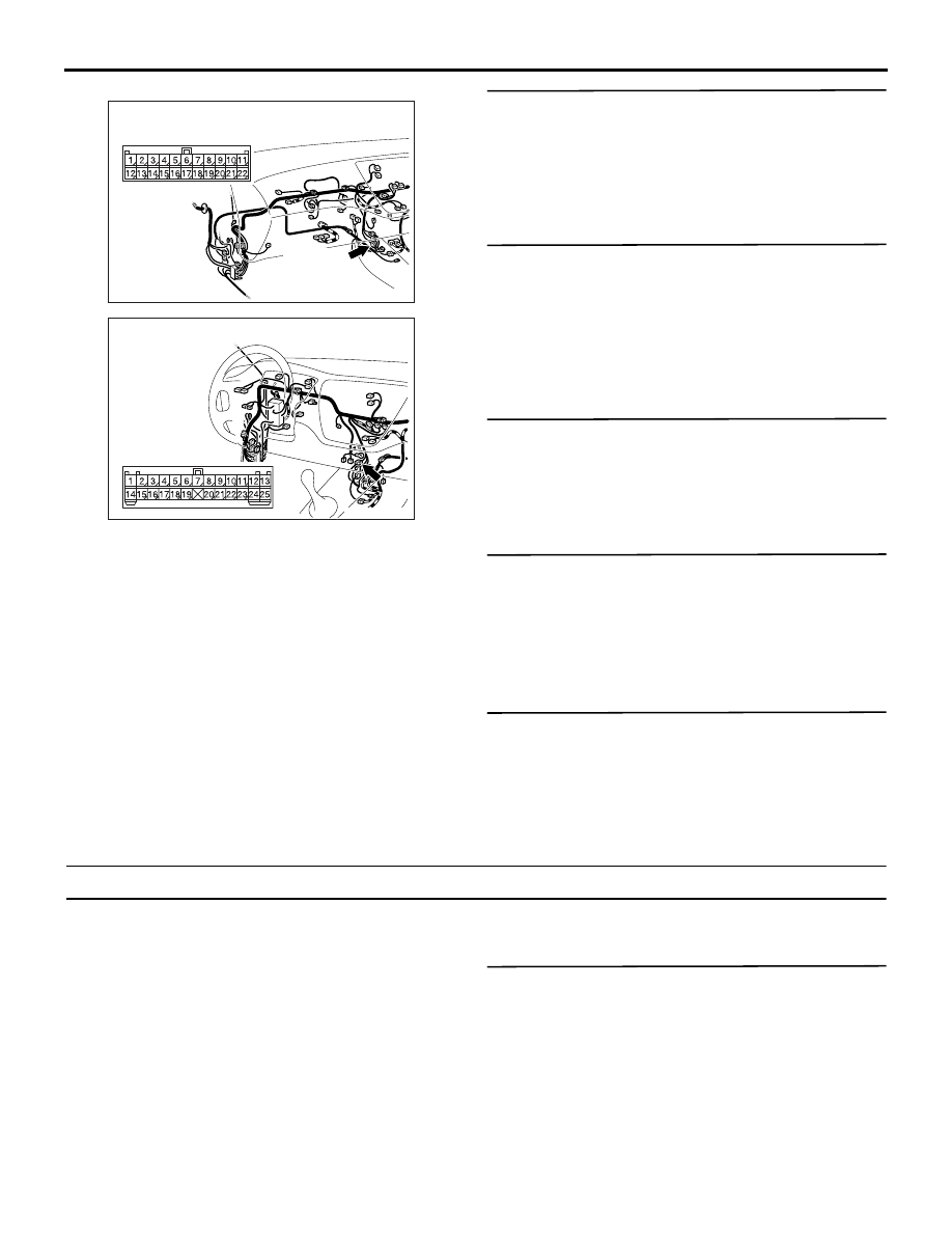
diate connector C-124 <LH drive vehicles> or C-122 
<RH drive vehicles>, and repair if necessary.

• Check the communication line for open or short 

circuit.

Q: Is the check result normal?

YES : 

Go to Step 17.

NO : 

Repair the wiring harness.

STEP 17. Check the magnetic clutch operation.
Refer to 

P.55-123

.

Q: Can the sound of the magnetic clutch (click) be 

heard?
YES : 

Go to Step 18.

NO : 

Replace the compressor magnet clutch.

STEP 18. Check the refrigerant temperature 
switch.
Refer to 

P.55-125

.

Q: Is the refrigerant temperature switch operating 

properly?
YES : 

Go to Step 19.

NO : 

Replace the refrigerant temperature switch.

STEP 19. Check the air thermo sensor.
Refer to 

P.55-120

.

Q: Is the air thermo sensor in good condition?

YES : 

Go to Step 20.

NO : 

Replace the air thermo sensor.

STEP 20. Check the refrigerant level.
Refer to 

P.55-104

.

Q: Is the refrigerant level correct?

YES : 

Go to Step 21.

NO : 

Correct the refrigerant level (Refer to 

P.55-104

).

STEP 21. Replace the A/C-ECU.
Check that the air conditioner works normally.

Q: Is the check result normal?

YES : 

The procedure is complete.

NO : 

Replace the engine-ECU.

Inspection Procedure 3: A/C Outlet Air Temperature cannot be set.

COMMENTS ON TROUBLE SYMPTOM

When the blower air temperature can not be 
changed even if the preset temperature is changed, 
the sensors, the air mixing damper control motor and 
potentiometer or the A/C-ECU may be defective.

PROBABLE CAUSE

• Malfunction of the A/C-ECU

DIAGNOSIS PROCEDURE

M.U.T.-II/III diagnosis code

Q: Is the diagnosis code set?

YES : 

Refer to diagnosis code chart 

P.55-5

.

NO : 

Replace the automatic A/C control panel 
(A/C-ECU).

AC504618AH

Connector: C-122 <RHD>

C-122 (L)

AC504622AD

Connector: C-124 <LHD>

TROUBLESHOOTING

HEATER, AIR CONDITIONER AND VENTILATION

55-42

Inspection Procedure 4: The Blower does not work.

COMMENTS ON TROUBLE SYMPTOM

If the blower motor does not operate, the blower 
motor circuit system may be defective.

PROBABLE CAUSES

• Malfunction of the blower motor (blower linear 

controller).

• Malfunction of the automatic A/C control panel 

(A/C-ECU)

• Damaged the wiring harness or connectors

DIAGNOSIS PROCEDURE

STEP 1. M.U.T.-II/III actuator test
Carry out the actuator test. (Refer to 

P.55-101

)

• Item 01, 02, 03, 04: Blower motor

Q: Does the blower motor work normally? 

YES : 

Replace the automatic A/C control panel 

(A/C-ECU).

NO : 

Go to Step 2.

Wire colour code
B : Black     LG : Light green     G : Green     L : Blue    W : White    
Y : Yellow     SB : Sky blue     BR : Brown    O : Orange     
GR : Grey     R : Red     P : Pink     V : Violet    PU : Purple

Blower Circuit

FUSIBLE
LINK

1

IGNITION
SWITCH (IG2)

BLOWER
RELAY

A/C-ECU

<RHD>

<LHD>

BLOWER MOTOR
(BLOWER
 LINEAR
 CONTROLLER)

TROUBLESHOOTING

HEATER, AIR CONDITIONER AND VENTILATION

55-43

STEP 2. Voltage measurement at the C-34 blower 
linear controller connector.

(1) Disconnect the connector, and measure at the 

wiring harness side.

(2) Turn the ignition switch to the ON position.

(3) Measure the voltage between terminal 6 and 

body earth.

OK: System voltage

Q: Is the check result normal?

YES : 

Go to Step 15.

NO : 

Go to Step 3.

STEP 3. Check the blower relay.
Refer to GROUP 55A, On-vehicle Service 

− Power 

relay check 

P.55-107

.

Q: Is the blower relay in good condition?

YES : 

Go to Step 4.

NO : 

Replace the blower relay.

STEP 4. Voltage measurement at C-216 blower 
relay connector.

(1) Remove the relay, and measure at the junction 

block side.

(2) Turn the ignition switch to the ON position.

(3) Voltage between terminal 1 and body earth.

OK: System voltage

Q: Is the check result normal?

YES : 

Go to Step 7.

NO : 

Go to Step 5.

AC504617AC

Connector: C-34 <LHD>

Harness side

AC504618AC

Connector: C-34 <RHD>

Harness side

AC301541JY

Connector C-34 
(Harness side)

AC504692AB

Connector: C-216 <LHD>

Junction block side

Junction block (Front view)

AC504694AB

Junction block (Front view)

Connector: C-216 <RHD>

Junction block side

AC301541JZ

Connector C-216
(Junction block side)

TROUBLESHOOTING

HEATER, AIR CONDITIONER AND VENTILATION

55-44

STEP 5. Connector check: C-216 blower relay 
connector

Q: Is the check result normal?

YES : 

Go to Step 6.

NO : 

Repair the connector.

STEP 6. Check the wiring harness between C-216 
blower relay connector terminal No.1 and the 
ignition switch (IG2).

NOTE: Prior to the wiring harness inspection, check 
junction block connector C-211, and repair if neces-
sary.

• Check the blower relay power supply line for 

open circuit.

Q: Is the check result normal?

YES : 

The trouble can be an intermittent 

malfunction (Refer to GROUP 00, How to 
Cope with Intermittent Malfunction 

P.00-5

).

NO : 

Repair the wiring harness.

AC504692AB

Connector: C-216 <LHD>

Junction block side

Junction block (Front view)

AC504694AB

Junction block (Front view)

Connector: C-216 <RHD>

Junction block side

AC504633AC

Connector: C-211, C-216 <LHD>

Junction block side

Junction block (Front view)

Harness side

C-211

C-211

C-216

C-216

AC504635AC

Harness side

Junction block (Front view)

C-211

C-216

Junction block side

C-216

C-211

Connector: C-211, C-216 <RHD>


Content   ..  540  541  542  543   ..