Mitsubishi Lancer Evolution IX. Manual - part 516
 

  Index      Mitsubishi     Mitsubishi Lancer Evolution IX - service repair manual


Search            


Content   ..  514  515  516  517   ..


Mitsubishi Lancer Evolution IX. Manual - part 516


TROUBLESHOOTING

ANTI-SKID BRAKING SYSTEM (ABS)

35B-95

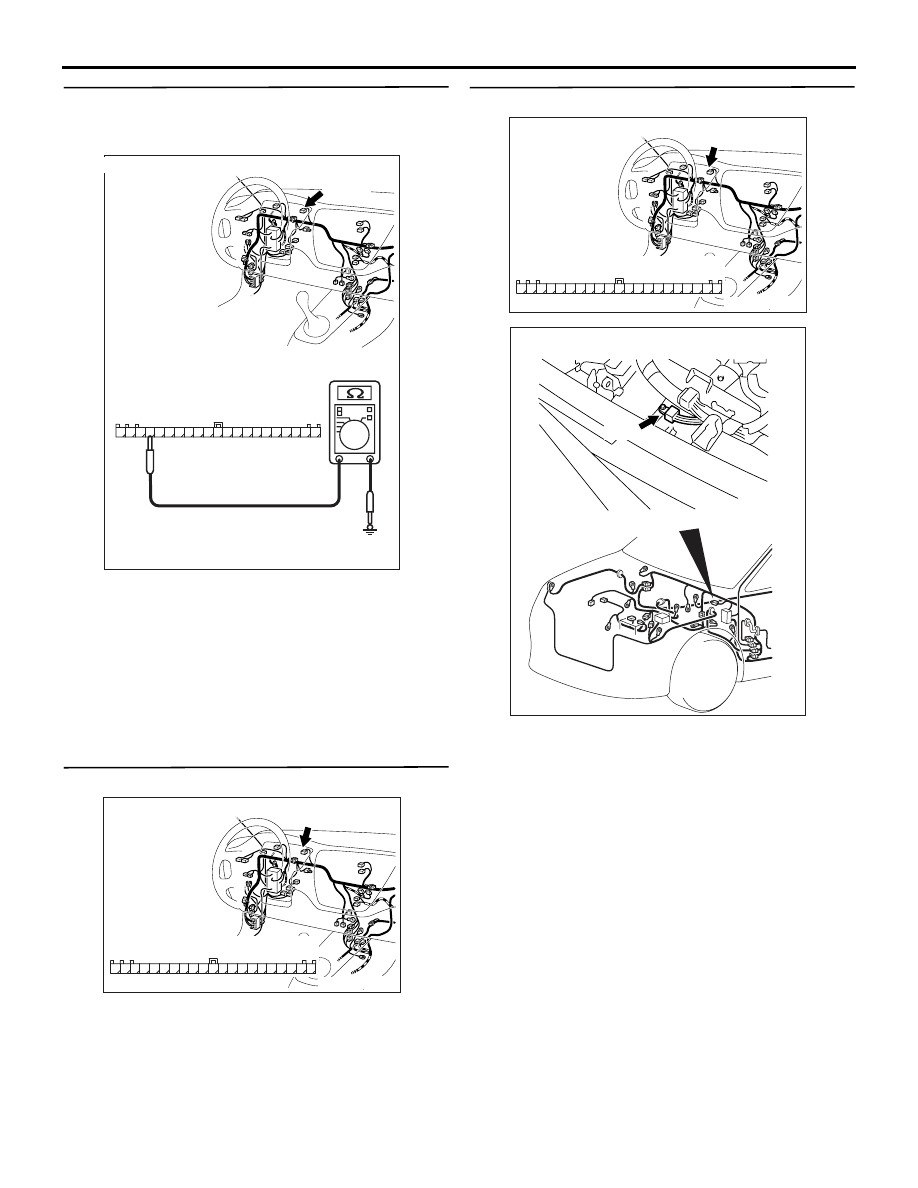
STEP 5. Check the earth circuit. Resistance 
measurement at combination meter connector 
C-02.

(1) Disconnect combination meter connector C-02 

and measure at the harness side.

(2) Measure the resistance between terminal 48 and 

earth.

OK: 2 ohms or less

Q: Is the resistance 2 ohms or less? 

YES : 

Go to Step 8.

NO : 

Go to Step 6.

STEP 6. Check the following connector.

Combination meter connector C-02
Check the connector for loose, corroded or damaged 
terminals, or terminals pushed back in the connector.

Q: Are the connector and terminals in good 

condition?
YES : 

Go to Step 7.

NO : 

Repair it and then go to Step 10.

STEP 7. Check the following harness wire.

The wire between combination meter connector C-02 
(terminal 48) and earth (No.7)

Q: Is the harness wire damaged?

YES : 

Repair or replace it and then go to Step 10.

NO : 

Go to Step 10.

AC212218AD

Connector: C-02

Connector C-02
(harness side)

31

43

37

34

32

33

35

36

40

38

39

41

42

48

44

45

4746

515049

C-02 (L)

AC211265

Connector: C-02 

31

43

37

34

32

33

35

36

40

38

39

41

42

48

44

45

4746

515049

Harness side

AI

AC211265

Connector: C-02 

31

43

37

34

32

33

35

36

40

38

39

41

42

48

44

45

4746

515049

Harness side

AI

AC211897AB

Earth

No.7

TROUBLESHOOTING

ANTI-SKID BRAKING SYSTEM (ABS)

35B-96

STEP 8. Check the following connectors.

Combination meter connector C-01

Intermediate connector C-122

ABS-ECU connector B-118
Check the connectors for loose, corroded or dam-
aged terminals, or terminals pushed back in the con-
nector.

Q: Are the connectors and terminals in good 

condition?
YES : 

Go to Step 9.

NO : 

Repair it and then go to Step 10.

STEP 9. Check the following harness wire.

The wire between combination meter connector C-01 
(terminal 13) and ABS-ECU connector B-118 (termi-
nal 27)

Q: Is the harness wire damaged?

YES : 

Repair or replace it and then go to Step 10.

NO : 

Replace the combination meter (Refer to 
GROUP 54A, Combination Meter Assembly 

P.54A-58

). Then go to Step 10.

STEP 10. Retest the system.

Q: Does the ABS warning lamp illuminate for 3 

seconds when the ignition switch is turned to the 
"ON" position with engine stopped or upon 
start-up?
YES : 

The procedure is complete.

NO : 

Return to Step 1.

AC211265DF

Connector: C-01

C-01

1

2

3

4

5

6

7

8

9

10

11

12

13

14

15

16

17

18

19

20

21

Harness side

AC211265 DD

Connector: C-122

C-122 (L)

2

1

3

13

12

14

21

10

5

4

6

16

15

17

7 8 9

19

18

20

11

22

AC211901AD

B-118 (B)

Connector: B-118

28

32

34

12

11

33

30

21

9

10

22

31

7

8

29

20 19

24

2

26

4

5

6

27

18 17

3

25

16 15

1

23

13

14

Harness side

AC211265DF

Connector: C-01

C-01

1

2

3

4

5

6

7

8

9

10

11

12

13

14

15

16

17

18

19

20

21

Harness side

AC211901AD

B-118 (B)

Connector: B-118

28

32

34

12

11

33

30

21

9

10

22

31

7

8

29

20 19

24

2

26

4

5

6

27

18 17

3

25

16 15

1

23

13

14

Harness side

TROUBLESHOOTING

ANTI-SKID BRAKING SYSTEM (ABS)

35B-97

INSPECTION PROCEDURE 4: The ABS Warning Lamp Remains Illuminated after the Engine is 
Started.

NOTE: This diagnosis procedure is limited to cases where communication with the M.U.T.-II is possible 
(ABS-ECU power supply is normal) and no diagnosis code is set.

ABS WARNING LAMP CIRCUIT

Refer to 

P.35B-92

.

CIRCUIT OPERATION

Refer to 

P.35B-92

.

COMMENT ON TROUBLE SYMPTOM

The cause is probably the ABS-ECU malfunction.

PROBABLE CAUSES

The most likely causes for this case are:

• Damaged wiring harness or connector

• Malfunction of the brake modulator hydraulic unit 

(integrated with ABS-ECU)

DIAGNOSIS

STEP 1. Check the following connectors.

Combination meter connector C-01

• Intermediate connector C-122

ABS-ECU connector B-118
Check the connectors for loose, corroded or dam-
aged terminals, or terminals pushed back in the con-
nector.

Q: Are the connectors and terminals in good 

condition?
YES : 

Go to Step 2.

NO : 

Repair it and then go to Step 4.

AC212218AF

Connectors: C-01, C-122

C-122 (L)

C-01

2

1

3

13

12

14

21

10

5

4

6

16

15

17

7 8 9

19

18

20

11

22

1

2

3

4

5

6

7

8

9

10

11

12

13

14

15

16

17

18

19

20

21

Connector C-01
(harness side)

Connector C-122

AC211901AD

B-118 (B)

Connector: B-118

28

32

34

12

11

33

30

21

9

10

22

31

7

8

29

20 19

24

2

26

4

5

6

27

18 17

3

25

16 15

1

23

13

14

Harness side

TROUBLESHOOTING

ANTI-SKID BRAKING SYSTEM (ABS)

35B-98

STEP 2. Check the following harness wire.

The wire between combination meter connector C-01 
(terminal 13) and ABS-ECU connector B-118 (termi-
nal 27)

Q: Is the harness wire damaged?

YES : 

Repair or replace it and then go to Step 4.

NO : 

Go to Step 3.

STEP 3. Check the ABS warning lamp circuit at 
ABS-ECU connector B-118.

(1) Disconnect ABS-ECU connector B-118 and 

check at the harness side connector.

(2) Turn the ignition switch to the "ON" position.
(3) Earth terminal 27 and check the ABS warning 

lamp.

Q: Does the ABS warning lamp go off?

YES : 

Replace the brake modulator hydraulic unit 

(integrated with ABS-ECU) (Refer to 

P.35B-143

). Then go to Step 4.

NO : 

Replace the combination meter (Refer to 
GROUP 54A, Combination Meter Assembly 

P.54A-58

). Then go to Step 4.

STEP 4. Retest the system.

Q: Does the ABS warning lamp turn off in 3 seconds 

after start-up?
YES : 

The procedure is complete.

NO : 

Return to Step 1.

AC211265DF

Connector: C-01

C-01

1

2

3

4

5

6

7

8

9

10

11

12

13

14

15

16

17

18

19

20

21

Harness side

AC211901AD

B-118 (B)

Connector: B-118

28

32

34

12

11

33

30

21

9

10

22

31

7

8

29

20 19

24

2

26

4

5

6

27

18 17

3

25

16 15

1

23

13

14

Harness side

AC212153

28

32

34

12

11

33

30

21

9

10

22

31

7

8

29

20 19

24

2

26

4

5

6

27

18 17

3

25

16 15

1

23

13

14

Connector B-118
(harness side)

AF

B-118 (B)

Connector: B-118


Content   ..  514  515  516  517   ..