Mitsubishi Lancer Evolution IX. Manual - part 503
 

  Index      Mitsubishi     Mitsubishi Lancer Evolution IX - service repair manual


Search            


Content   ..  501  502  503  504   ..


Mitsubishi Lancer Evolution IX. Manual - part 503


TROUBLESHOOTING

ANTI-SKID BRAKING SYSTEM (ABS)

35B-43

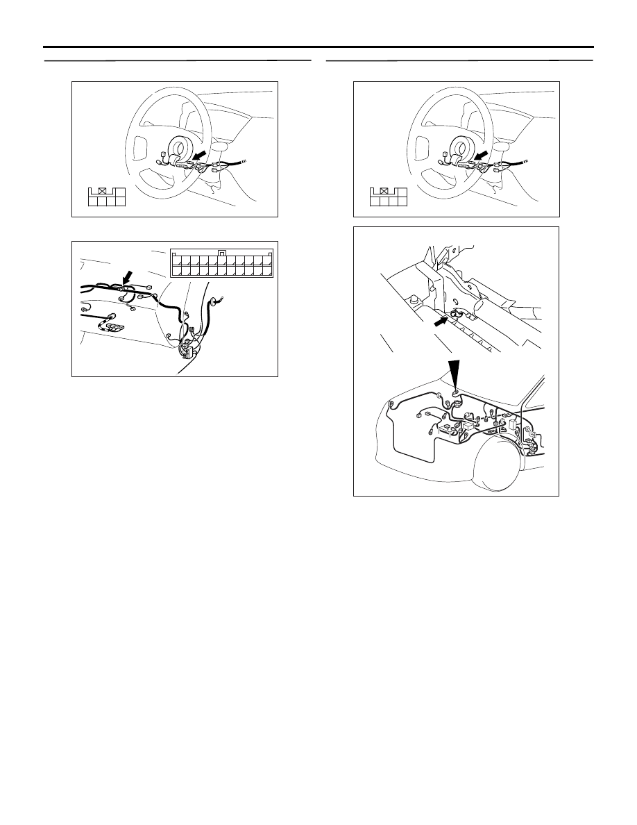
STEP 6. Check the following connectors.

Steering wheel sensor connector C-230

Joint connector C-06
Check the connectors for loose, corroded or dam-
aged terminals, or terminals pushed back in the con-
nector.

Q: Are the connectors and terminals in good 

condition?
YES : 

Go to Step 7.

NO : 

Repair it and then go to Step 11.

STEP 7. Check the following harness wires.

AC211267AL

Connector: C-230

Harness side

5 4

1
2

3

AC211266BP

Connector: C-06

C-06 (GR)

2

1

3

13

12

14

21

10

5

4

6

16

15

17

7 8 9

19

18

20

11

22

AC211267AL

Connector: C-230

Harness side

5 4

1
2

3

AC211896 AB

Earth

No.3

TROUBLESHOOTING

ANTI-SKID BRAKING SYSTEM (ABS)

35B-44

The wire between steering wheel sensor connector 
C-230 (terminal 3) and earth (No.3, No.14)

Q: Is any harness wire damaged?

YES : 

Repair or replace it and then go to Step 11.

NO : 

Go to Step 11.

STEP 8. Check steering wheel sensor output 
voltage.

(1) Connect steering wheel sensor connector C-230.
(2) Turn the ignition switch to the "ON" position.

(3) Measure the voltage, by backprobing, between 

terminal 1 and earth, terminal 4 and earth, and 
terminal 5 and earth.

OK: The voltage should measure as indi-
cated in the figure.

Q: Is the steering wheel sensor output voltage 

normal?
YES : 

Go to Step 9.

NO : 

Replace the steering wheel sensor (Refer to 

P.35B-150

). Then go to Step 11.

AC211898AB

Earth

NO.14

AC212249AD

Connector: C-230

Connector C-230
(Harness side)

5 4

1
2

3

AC211894

Time

AB

Voltage

2.7 - 4.4 V

0.8 - 2.1 V

Variations in voltage when turning the
steering wheel 

TROUBLESHOOTING

ANTI-SKID BRAKING SYSTEM (ABS)

35B-45

STEP 9. Check the following connectors.

Steering wheel sensor connector C-230

Intermediate connector C-122

ABS-ECU connector B-118
Check the connectors for loose, corroded or dam-
aged terminals, or terminals pushed back in the con-
nector.

Q: Are the connectors and terminals in good 

condition?
YES : 

Go to Step 10.

NO : 

Repair it and then go to Step 11.

STEP 10. Check the following harness wires.

If diagnosis code No.81 (ST-1) is set: The wire 

between steering wheel sensor connector C-230 
(terminal 5) and ABS-ECU connector B-118 (ter-
minal 26)

• If diagnosis code No.82 (ST-2) is set: The wire 

between steering wheel sensor connector C-230 
(terminal 4) and ABS-ECU connector B-118 (ter-
minal 17)

• If diagnosis code No.83 (ST-N) is set: The wire 

between steering wheel sensor connector C-230 
(terminal 1) and ABS-ECU connector B-118 (ter-
minal 4)

Q: Is any harness wire damaged?

YES : 

Repair or replace it and then go to Step 11.

NO : 

Replace the brake modulator hydraulic unit 
(integrated with ABS-ECU) (Refer to 

P.35B-143

). Then go to Step 11.

AC211267AL

Connector: C-230

Harness side

5 4

1
2

3

AC211265 DD

Connector: C-122

C-122 (L)

2

1

3

13

12

14

21

10

5

4

6

16

15

17

7 8 9

19

18

20

11

22

AC211901AD

B-118 (B)

Connector: B-118

28

32

34

12

11

33

30

21

9

10

22

31

7

8

29

20 19

24

2

26

4

5

6

27

18 17

3

25

16 15

1

23

13

14

Harness side

AC211267AL

Connector: C-230

Harness side

5 4

1
2

3

AC211901AD

B-118 (B)

Connector: B-118

28

32

34

12

11

33

30

21

9

10

22

31

7

8

29

20 19

24

2

26

4

5

6

27

18 17

3

25

16 15

1

23

13

14

Harness side

TROUBLESHOOTING

ANTI-SKID BRAKING SYSTEM (ABS)

35B-46

STEP 11. Check whether the diagnosis code is 
reset.

Check again if the diagnosis code is set.
(1) Turn the ignition switch to the "ON" position.

(2) Erase the diagnosis code.
(3) Turn the ignition switch to the "LOCK" (OFF) 

position.

(4) Turn the ignition switch to the "ON" position.
(5) Check if the diagnosis code is set.
(6) Turn the ignition switch to the "LOCK" (OFF) 

position.

Q: Does diagnosis code No.81, 82 and/or 83 reset?

YES : 

Return to Step 1.

NO : 

The procedure is complete.

AC207179AB

M.U.T.-II

16-PIN

<Using the M.U.T.-II>

AC210056

AC

MB991911

16-PIN

MB991827

MB991824 

<Using the M.U.T.-III>


Content   ..  501  502  503  504   ..