Mitsubishi Lancer Evolution IX. Manual - part 490
 

  Index      Mitsubishi     Mitsubishi Lancer Evolution IX - service repair manual


Search            


Content   ..  488  489  490  491   ..


Mitsubishi Lancer Evolution IX. Manual - part 490


BRAKE PEDAL

SERVICE BRAKES

35A-15

INSTALLATION SERVICE POINT
>>A<< BRAKE PEDAL ASSEMBLY 
INSTALLATION

AC006234 AB

A

A

B

B

Tighten the brake booster mounting nuts (A), and 
then the brake pedal assembly mounting bolts (B).
NOTE: The brake pedal assembly cannot be posi-
tioned correctly if the brake pedal assembly mount-
ing bolts (B) are tightened first, as their holes are 
oblong holes.

INSPECTION

M1351003500254

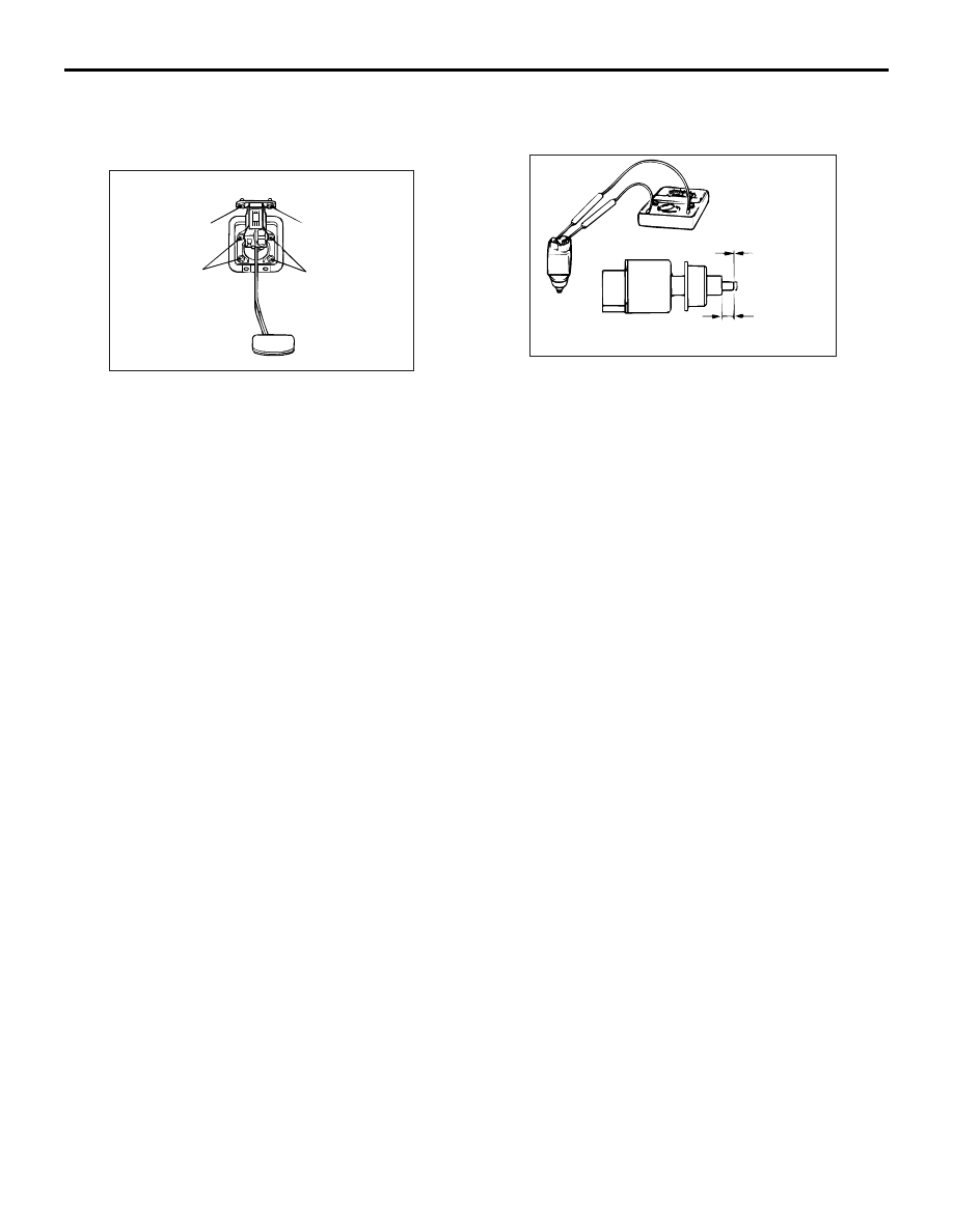
STOPLAMP SWITCH CHECK

AC006235AB

4 mm

No continuity

Continuity

1. Connect an ohmmeter between the stop lamp 

switch connector terminals.

2. There should be no continuity between the 

terminals when the plunger is pushed in as 
shown. There should be continuity when it is 
released.

MASTER CYLINDER ASSEMBLY AND BRAKE BOOSTER

SERVICE BRAKES

35A-16

MASTER CYLINDER ASSEMBLY AND BRAKE BOOSTER

REMOVAL AND INSTALLATION

M1351003700537

Pre-removal Operation
• Brake Fluid Draining
• Air Intake Hose and Air Cleaner Removal (Refer to 

GROUP 15, Air Cleaner 

P.15-5

).

• Strut Tower Bar Removal (Refer to GROUP 42, Strut 

Tower Bar 

P.42-9

).

Post-installation Operation
• Brake Pedal Adjustment (Refer to 

P.35A-5

).

• Air Intake Hose and Air Cleaner Installation (Refer to 

GROUP 15, Air Cleaner 

P.15-5

).

• Strut Tower Bar Removal (Refer to GROUP 42, Strut 

Tower Bar 

P.42-9

).

• Brake Fluid Supplying and Air Bleeding (Refer to 

P.35A-7

).

AC310837

3M ATD part No. 8661 or equivalent

AB

13

16 ± 1 N·m

13

8

15 ± 2 N·m

10 ± 2 N·m

15 ± 2 N·m

22 ± 3 N·m

14 ± 3 N·m

7

9

11

10

7

6

2

4

1

12

5

5

3

7

13

16 ± 1 N·m

Master cylinder removal steps 

1.

Clutch hose connection

2.

Brake fluid level indicator switch 
connector

3.

Brake fluid reservoir cap

4.

Brake fluid level indicator switch

5.

Brake tube connection

6.

Brake master cylinder assembly
Brake booster removal steps 

1.

Clutch hose connection

2.

Brake fluid level indicator switch 
connector

5.

Brake tube connection

6.

Brake master cylinder assembly

>>

B

<<

Push rod protrusion amount check 

and adjustment

>>

A

<<

7.

Brake booster vacuum hose 


(With built-in check valve)

8.

Brake booster pin

9.

Brake booster pin assembly

10. Clevis

Remove A/C liquid pipe B from the 

retaining clip (Refer to GROUP 55, 

Refrigerant Line 

P.55-128

).

11. Brake booster assembly
12. Brake booster body seal

Brake booster removal steps 

Fitting removal steps 

>>

A

<<

7.

Brake booster vacuum hose


(With built-in check valve)

13. Brake booster vacuum hose fitting 

MASTER CYLINDER ASSEMBLY AND BRAKE BOOSTER

SERVICE BRAKES

35A-17

INSTALLATION SERVICE POINTS
>>A<< BRAKE BOOSTER VACUUM HOSE 
CONNECTION

Insert the brake booster vacuum hose to the brake 
booster assembly with its paint mark facing upward, 
and then secure the hose by using the hose clip.

>>B<< PUSH ROD PROTRUSION 
AMOUNT CHECK AND ADJUSTMENT

AC006237AB

A

Measuring distance A

Block gauge

1. Measure dimension (A).

Standard value (A): 8.98 

 9.23 mm

NOTE: When a negative pressure of 66.7 kPa is 
applied to the brake booster, the push rod should 
protrude 10.27 - 10.53 mm.

AC006238AB

MB991568

Angle-nose pliers

Rod spline

2. If the protrusion amount is not within the standard 

value range, adjust the push rod length by turning 
the push rod. Use special tool push rod adjusting 
socket (MB991568) to turn the push rod while 
holding the rod spline with angle-nose pliers.

MASTER CYLINDER ASSEMBLY AND BRAKE BOOSTER

SERVICE BRAKES

35A-18

MASTER CYLINDER

M1351004200449

DISASSEMBLY AND REASSEMBLY

AC006239

2

3

1

4

6

7

5

10

N

9

N

8

N

10

9

8

Master cylinder kit

9

Brake fluid: DOT 3 or DOT 4

3

7

8

AB

Disassembly steps 

1. Brake fluid reservoir cap
2. Brake fluid reservoir filter
3. Brake master cylinder pin
4. Brake fluid reservoir
5. Brake master cylinder to reservoir 

seal

6. Brake master cylinder pin
7. Piston retainer
8. Primary piston assembly

9. Secondary piston assembly
10. Master cylinder body

INSPECTION

M1351004300338

• Check the inner surface of master cylinder body 

for rust or pitting.

• Check the primary and secondary pistons for 

rust, scoring, wear or damage.

• Check the diaphragm for cracks and wear.

Disassembly steps (Continued)


Content   ..  488  489  490  491   ..