Mitsubishi Lancer Evolution IX. Manual - part 469
 

  Index      Mitsubishi     Mitsubishi Lancer Evolution IX - service repair manual


Search            


Content   ..  467  468  469  470   ..


Mitsubishi Lancer Evolution IX. Manual - part 469


TROUBLESHOOTING

MULTIPORT FUEL INJECTION (MPI)

13A-351

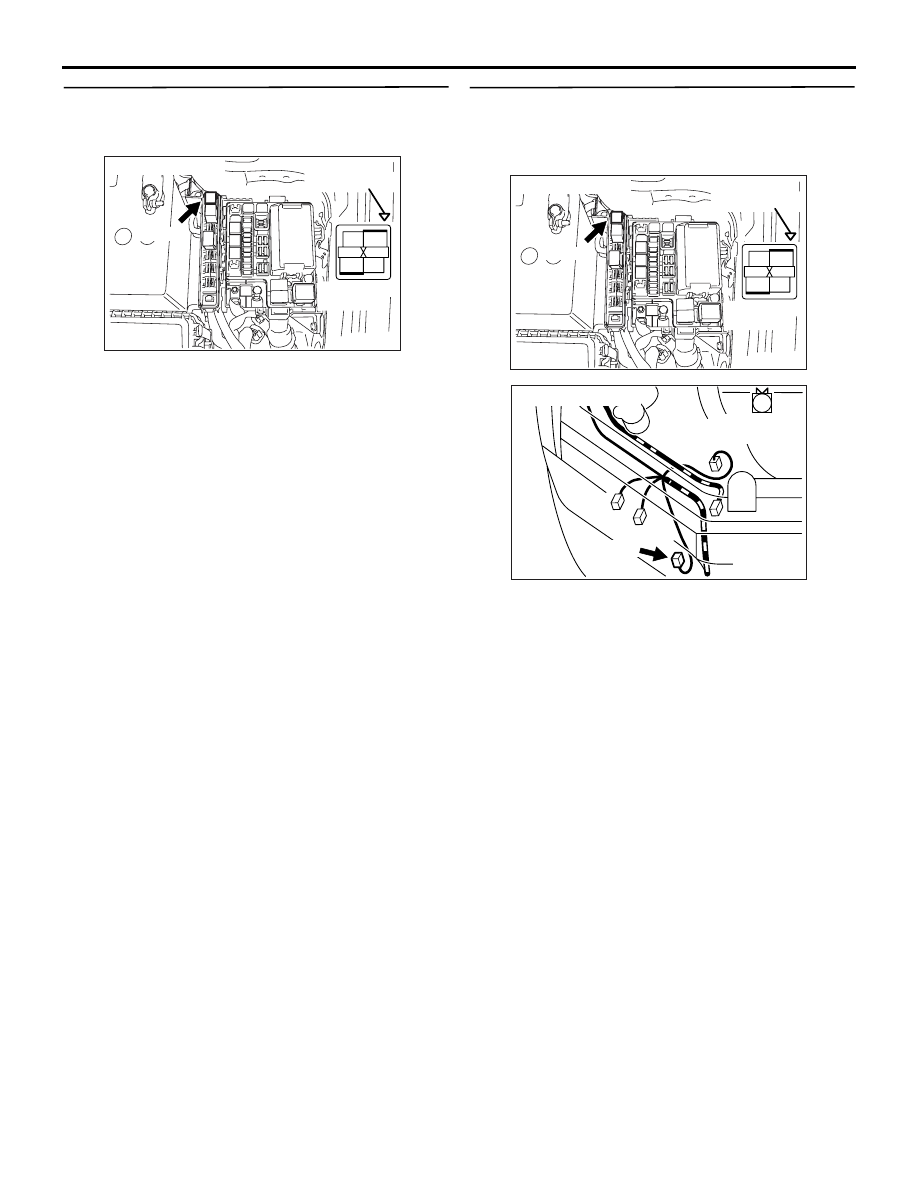
STEP 16. Check harness between battery and 
B-13X (terminal No. 1) A/C compressor relay 
connector.

NOTE: Before checking harness, check intermediate 
connector A-29

*1

or C-31

*2

, and repair if necessary.

• Check power supply line for damage.

Q: Is the check result normal?

YES : 

Go to Step 17 .

NO : 

Repair the damaged harness wire.

STEP 17. Check harness between B-13X 
(terminal No. 4) A/C compressor relay connector 
and A-36 (terminal No. 1) A/C compressor 
assembly connector.

NOTE: Before checking harness, check intermediate 
connector A-13

*1

or C-31

*2

, and repair if necessary.

• Check output line for damage.

Q: Is the check result normal?

YES : 

Replace the A/C compressor magnet clutch.

NO : 

Repair the damaged harness wire.

AK305270

2

1

3

4

B-13X

Connector: B-13X

AB

Harness side
connector

Relay box’s
triangle marks

AK305270

2

1

3

4

B-13X

Connector: B-13X

AB

Harness side
connector

Relay box’s
triangle marks

AK502005

1

AB

Connector: A-36

Harness side 
connector

A-36 (B)

TROUBLESHOOTING

MULTIPORT FUEL INJECTION (MPI)

13A-352

Inspection Procedure 29: A/C Load Signal System

OPERATION

• The A/C load signal is inputted to the 

engine-ECU (terminal No. 65) from the A/C-ECU 
(terminal No. 32).

FUNCTION

• The magnitude of the A/C compressor load is 

detected and input to the engine-ECU. The 
engine-ECU provides A/C idle up control accord-
ing to the A/C compressor load condition.

PROBABLE CAUSES

• Failed A/C-ECU

• Open/short circuit in A/C load signal circuit or 

loose connector contact

• Failed engine-ECU

AK501834

65

43
50

42
49

41
48
60 61

64

46 47
58 59
67 68

45

56
66

52

51

44

53

62

54

63

57

55

21
29

22
30

23
31

24
32

25
33

26
34

27
35

28
36

65

Engine-ECU

A/C-ECU

A/C load signal circuit

G-Y

G-Y

Wire colour code
B: Black  LG: Light green  G: Green  L: Blue  W: White  Y: Yellow  SB: Sky blue  BR: Brown  O: Orange  GR: Gray
R: Red  P: Pink  V: Violet  PU: Purple

AB

C-37

(MU801584)

C-119

(MU803782)

32

5<C-124>

 (*1) or 4<C-122> (*2)

NOTE

*1: L.H. drive vehicles
*2: R.H. drive vehicles

TROUBLESHOOTING

MULTIPORT FUEL INJECTION (MPI)

13A-353

DIAGNOSIS PROCEDURE

STEP 1. Perform voltage measurement at C-121 
engine-ECU connector.

• Measure engine-ECU terminal voltage.

• Engine: Idling

• A/C switch: ON (A/C compressor in driven state)

• Voltage between terminal No. 65 and earth

OK:

1 V or less (when the A/C is under low load)
System voltage (when the A/C is under high 

load)

Q: Is the check result normal?

YES : 

Go to Step 2 .

NO : 

Go to Step 4 .

STEP 2. Connector check: C-121 engine-ECU 
connector

Q: Is the check result normal?

YES : 

Go to Step 3 .

NO : 

Repair or replace the connector.

STEP 3. Check the trouble symptoms.

Q: Does trouble symptom persist?

YES : 

Replace the engine-ECU.

NO : 

Intermittent malfunction (Refer to GROUP 
00 

− How to Use 

Troubleshooting/Inspection Service Points 

P.00-5

).

AK501995

2

3

4

5

6

7

8

9

11

12

13

14

15

16

17

18

19

20

30

21

22

23

24

25

26

27

28

29

31

32

33

34

35

1

10

AB

Connector: C-121

C-121 (GR)

C-121 (GR)

Harness side connector

<L. H. drive vehicles>

<R. H. drive vehicles>

AK501995

2

3

4

5

6

7

8

9

11

12

13

14

15

16

17

18

19

20

30

21

22

23

24

25

26

27

28

29

31

32

33

34

35

1

10

AB

Connector: C-121

C-121 (GR)

C-121 (GR)

Harness side connector

<L. H. drive vehicles>

<R. H. drive vehicles>

TROUBLESHOOTING

MULTIPORT FUEL INJECTION (MPI)

13A-354

STEP 4. Connector check: C-121 engine-ECU 
connector 

Q: Is the check result normal?

YES : 

Go to Step 5 .

NO : 

Repair or replace the connector.

STEP 5. Perform voltage measurement at C-37 
A/C-ECU connector.

• Measure A/C-ECU terminal voltage.

• Engine: Idling

• A/C switch: ON (A/C compressor in driven state)

• Voltage between terminal No. 32 and earth

OK: System voltage (when the A/C is under 
high load)

Q: Is the check result normal?

YES : 

Go to Step 8 .

NO : 

Go to Step 6 .

STEP 6. Connector Check: C-37 A/C-ECU 
connector

Q: Is the check result normal?

YES : 

Go to Step 7 .

NO : 

Repair or replace the connector.

AK501995

2

3

4

5

6

7

8

9

11

12

13

14

15

16

17

18

19

20

30

21

22

23

24

25

26

27

28

29

31

32

33

34

35

1

10

AB

Connector: C-121

C-121 (GR)

C-121 (GR)

Harness side connector

<L. H. drive vehicles>

<R. H. drive vehicles>

AK502007

28
36

27
35

26
34

25
33

24
32

23
31

22
30

21
29

AB

C-37 (B)

Harness side 
connector

Connector: C-37

AK502007

28
36

27
35

26
34

25
33

24
32

23
31

22
30

21
29

AB

C-37 (B)

Harness side 
connector

Connector: C-37


Content   ..  467  468  469  470   ..