Mitsubishi Lancer Evolution IX. Manual - part 453
 

  Index      Mitsubishi     Mitsubishi Lancer Evolution IX - service repair manual


Search            


Content   ..  451  452  453  454   ..


Mitsubishi Lancer Evolution IX. Manual - part 453


TROUBLESHOOTING

MULTIPORT FUEL INJECTION (MPI)

13A-287

Inspection Procedure 16: Ignition Timing Offset

COMMENT ON TROUBLE SYMPTOM

• Failure is possibly caused by failed crank angle 

sensor, failed exhaust camshaft position sensor, 
improper installed timing belt or other faults.

PROBABLE CAUSE

• Failed crank angle sensor 

• Failed exhaust camshaft position sensor 

• Improperly installed timing belt

• Failed engine-ECU 

DIAGNOSIS PROCEDURE

STEP 1. M.U.T.-II/III diagnosis code

Q: Diagnosis code set?

YES : 

Inspection chart for diagnosis code (Refer 

to 

P.13A-17

).

NO : 

Go to Step 2 .

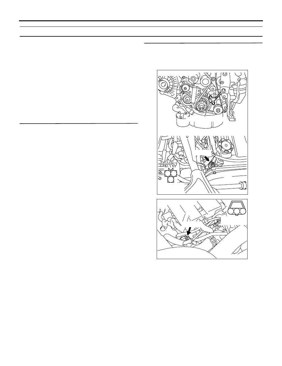
STEP 2. Perform output wave pattern 
measurement of crank angle sensor and exhaust 
camshaft position sensor (Using an 
oscilloscope).

Crank Angle Sensor

• Use special tool test harness (MD998478) to con-

nect B-117 crank angle sensor connector, and 
measure at pick-up harness.

• Engine: Idling

• Transmission: Neutral

• Voltage between terminal No. 2 and earth.

Exhaust camshaft Position Sensor

• Use special tool test harness (MB991709) to con-

nect B-106 exhaust camshaft position sensor 
connector, and measure at pick-up harness.

• Engine: Idling

• Transmission: Neutral

• Voltage between terminal No. 2 and earth.

AK305020

1

2

3

AB

Connector : B-117

Harness side 
connector

B-117(B)

Crank angle sensor

AK501999

1

2

3

AB

Connector: B-106

B-106 (B)

Harness side 
connector

TROUBLESHOOTING

MULTIPORT FUEL INJECTION (MPI)

13A-288

OK: Output waveform timings of both sen-
sors are the same as the check procedure 
(Refer to 

P.13A-385

) using an oscilloscope.

Q: Is the check result normal?

YES : 

Go to Step 3 .

NO : 

Go to Step 4 .

STEP 3. Check the trouble symptoms.

Q: Does trouble symptom persist?

YES : 

Replace the engine-ECU.

NO : 

Intermittent malfunction (Refer to GROUP 
00 

− How to Use 

Troubleshooting/Inspection Service Points 

P.00-5

).

STEP 4. Check crank angle sensor and exhaust 
camshaft position sensor mounted conditions.

Q: Is the check result normal? 

YES : 

Go to Step 5 .

NO : 

Repair.

STEP 5. Check timing marks of timing belt.

Q: Is the check result normal?

YES : 

Go to Step 6 .

NO : 

Align timing marks.

STEP 6. Check crank angle sensor vane.

Q: Is the check result normal? 

YES : 

Go to Step 7 .

NO : 

Replace the crank angle sensor vane.

STEP 7. Check exhaust camshaft position 
sensing cylinder.

Q: Is the check result normal? 

YES : 

Go to Step 8 .

NO : 

Replace the exhaust camshaft position 
sensing cylinder.

STEP 8. Replace crank angle sensor.

• After replacing the crank angle sensor, re-check 

the trouble symptoms.

Q: Does trouble symptom persist?

YES : 

Go to Step 9 .

NO : 

The check is end.

STEP 9. Replace exhaust camshaft position 
sensor.

• After replacing the exhaust camshaft position 

sensor, re-check the trouble symptoms.

Q: Does trouble symptom persist?

YES : 

Replace the engine-ECU.

NO : 

Intermittent malfunction (Refer to GROUP 
00 

− How to Use 

Troubleshooting/Inspection Service Points 

P.00-5

).

Inspection Procedure 17: Run on (Dieseling)

COMMENT ON TROUBLE SYMPTOM

• Failure is possibly caused by leakage from injec-

tor.

PROBABLE CAUSES

• Failed injector

• Failed engine-ECU

DIAGNOSIS PROCEDURE

STEP 1. Check injector for spray condition.

• Check each injector for spray condition (Refer to 

P.13A-406

).

Q: Does trouble symptom persist?

YES : 

Replace the engine-ECU.

NO : 

Replace the injector.

TROUBLESHOOTING

MULTIPORT FUEL INJECTION (MPI)

13A-289

Inspection Procedure 18: Odor, White Smoke, Black Smoke, and High-Concentration CO/HC During 
Idling

COMMENT ON TROUBLE SYMPTOM

• Failure is possibly caused by improper air-fuel 

ratio, deteriorated catalyst, failed ignition system, 
failed fuel system, failed compression pressure or 
other faults.

PROBABLE CAUSES

• Failed air-fuel control system

• Failed ignition system

• Failed fuel system

• Failed intake and exhaust system

• Failed emission control system

• Failed compression pressure

• Failed catalytic converter

• Failed engine-ECU

DIAGNOSIS PROCEDURE

STEP 1. M.U.T.-II/III diagnosis code

Q: Diagnosis code set?

YES : 

Inspection chart for diagnosis code (Refer 

to 

P.13A-17

).

NO : 

Go to Step 2 .

STEP 2. Check injector for operating sound.

• Check injector for operating sound (Refer to 

P.13A-406

).

Q: Can operating sound be heard?

YES : 

Go to Step 3 .

NO : 

Check the injector system of the defective 

cylinder.

(Refer to Code No. P0201: No. 1 injector 

system 

P.13A-105

).

(Refer to Code No. P0202: No. 2 injector 

system 

P.13A-111

).

(Refer to Code No. P0203: No. 3 injector 

system 

P.13A-117

).

(Refer to Code No. P0204: No. 4 injector 

system 

P.13A-123

).

STEP 3. Check ignition timing.

• Check ignition timing (Refer to GROUP 11A − 

On-vehicle Service 

P.11A-9

).

Q: Is the check result normal?

YES : 

Go to Step 4 .

NO : 

Check for offset ignition timing (Refer to 
Inspection Procedure 16 

P.13A-287

).

STEP 4. M.U.T.-II/III data list

• Refer to Data List Reference Table 

P.13A-372

.

a. Item No. 12: Air flow sensor
b. Item No. 13: Intake air temperature sensor

c. Item No. 21: Engine coolant temperature sen-

sor

d. Item No. 25: Barometric pressure sensor

Q: Are the check results normal?

YES : 

Go to Step 5 .

NO : 

Perform the diagnosis code classified check 
procedure for the sensor that has shown an 
abnormal data value (Refer to Inspection 
Chart for Diagnosis Codes 

P.13A-17

).

STEP 5. Check air intake from intake hose and 
intake manifold.

Q: Is the check result normal?

YES : 

Go to Step 6 .

NO : 

Repair.

STEP 6. Check for emission leakage from 
exhaust manifold.

Q: Is the check result normal?

YES : 

Go to Step 7 .

NO : 

Repair.

STEP 7. Check throttle body (throttle valve 
portion) for contamination.

Q: Is the check result normal?

YES : 

Go to Step 8 .

NO : 

Clean throttle body (throttle valve portion) 
(Refer to 

P.13A-395

).

STEP 8. M.U.T.-II/III data list

• Refer to Data List Reference Table 

P.13A-372

.

a. Item No. 11: Oxygen sensor (front)

Q: Is the check result normal?

YES : 

Go to Step 9 .

NO : 

Check oxygen sensor (front) system (Refer 

to Code No. P0130 

P.13A-75

).

TROUBLESHOOTING

MULTIPORT FUEL INJECTION (MPI)

13A-290

STEP 9. Check Purge control solenoid valve 
itself.

• Check Purge control solenoid valve itself (Refer 

to GROUP 17 

− Emission Control System − 

Evaporative Emission Control System 

P.17-11

).

Q: Is the check result normal?

YES : 

Go to Step 10 .

NO : 

Replace the purge control solenoid valve.

STEP 10. Check EGR control solenoid valve 
itself.

• Check the EGR control solenoid valve itself 

(Refer to GROUP 17 

− Emission Control System 

− Exhaust Gas Recirculation (EGR) System 

P.17-15

).

Q: Is the check result normal?

YES : 

Go to Step 11 .

NO : 

Replace the EGR control solenoid valve.

STEP 11. Check EGR valve itself.

• Check EGR valve itself (Refer to GROUP 17 − 

Emission Control System 

− Exhaust Gas Recir-

culation (EGR) System 

P.17-15

).

Q: Is the check result normal?

YES : 

Go to Step 12 .

NO : 

Replace the EGR valve.

STEP 12. Fuel pressure measurement.

• Fuel pressure measurement (Refer to 

P.13A-396

).

Q: Is the check result normal?

YES : 

Go to Step 13 .

NO : 

Repair.

STEP 13. Check positive crankcase ventilation 
valve itself.

• Check positive crankcase ventilation valve itself 

(Refer to GROUP 17 

− Emission Control System 

− Evaporative Emission Control System 

P.17-9

).

Q: Is the check result normal?

YES : 

Go to Step 14 .

NO : 

Replace the positive crankcase ventilation 
valve.

STEP 14. Check spark plug.

Q: Is the check result normal?

YES : 

Go to Step 15 .

NO : 

Replace the spark plug.

STEP 15. Check spark plug cable itself.

• Check spark plug cable itself (Refer to GROUP 

16 

− Ignition System − On-vehicle Service 

P.16-29

).

Q: Is the check result normal?

YES : 

Go to Step 16 .

NO : 

Replace the spark plug cable.

STEP 16. Check ignition coil itself.

• Check ignition coil itself (Refer to GROUP 16 − 

Ignition System 

 On-vehicle Service 

P.16-28

).

Q: Is the check result normal?

YES : 

Go to Step 17 .

NO : 

Replace the ignition coil.

STEP 17. Check compression pressure.

• Check compression pressure (Refer to GROUP 

11A 

− On-vehicle Service 

P.11A-11

).

Q: Is the check result normal?

YES : 

Go to Step 18 .

NO : 

Repair.

STEP 18. Check injector for spraying condition.

• Check each injector for spray condition (Refer to 

P.13A-406

).

Q: Does trouble symptom persist?

YES : 

Go to Step 19 .

NO : 

Replace the injector.

STEP 19. Replace catalytic converter.

• After replacing the catalytic converter re-check 

the trouble symptoms.

Q: Does trouble symptom persist?

YES : 

Replace the engine-ECU.

NO : 

The check is end.


Content   ..  451  452  453  454   ..