Mitsubishi Lancer Evolution IX. Manual - part 389
 

  Index      Mitsubishi     Mitsubishi Lancer Evolution IX - service repair manual


Search            


Content   ..  387  388  389  390   ..


Mitsubishi Lancer Evolution IX. Manual - part 389


TROUBLESHOOTING

MULTIPORT FUEL INJECTION (MPI)

13A-31

STEP 17. Perform voltage measurement at B-105 
air flow sensor connector.

• Use special tool test harness (MB991709) to con-

nect connector, and measure at pick-up harness.

• Transmission: Neutral

• Voltage between terminal No. 7 and earth.

OK:

 1 V (Engine: Idling)

 9 V (Engine: 3,000 r/min.)

Q: Is the check result normal?

YES : 

Go to Step 20 .

NO : 

Go to Step 18 .

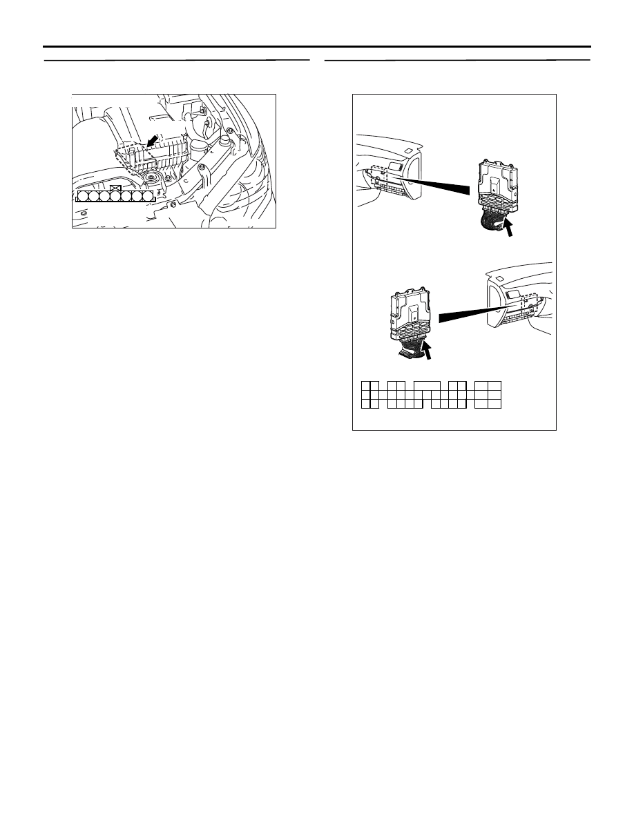
STEP 18. Connector check: C-121 engine-ECU 
connector

Q: Is the check result normal?

YES : 

Go to Step 19 .

NO : 

Repair or replace the connector.

AK305005

3

4

5

1

2

6

7

AB

Connector : B-105

Harness side 
connector

B-105(B)

AK501995

2

3

4

5

6

7

8

9

11

12

13

14

15

16

17

18

19

20

30

21

22

23

24

25

26

27

28

29

31

32

33

34

35

1

10

AB

Connector: C-121

C-121 (GR)

C-121 (GR)

Harness side connector

<L. H. drive vehicles>

<R. H. drive vehicles>

TROUBLESHOOTING

MULTIPORT FUEL INJECTION (MPI)

13A-32

STEP 19. Check harness between B-105 (terminal 
No. 7) air flow sensor connector and C-121 
(terminal No. 19) engine-ECU connector.

• Check reset signal line for open circuit and dam-

age.

Q: Is the check result normal?

YES : 

Go to Step 8 .

NO : 

Repair the damaged harness wire.

STEP 20. Perform output wave pattern 
measurement at B-105 air flow sensor connector 
(Using an oscilloscope).

• Use special tool test harness (MB991709) to con-

nect connector, and measure at pick-up harness. 

• Engine: Idling

• Transmission: Neutral

• Voltage between terminal No. 3 and earth.

OK: Waveforms should be displayed on 
inspection procedure using an oscilloscope 
(Refer to 

P.13A-385

) and noise should not be 

displayed in the waveform.

Q: Is the check result normal?

YES : 

Go to Step 8 .

NO : 

Go to Step 21 .

STEP 21. Replace the air flow sensor.

• After replacing the air flow sensor, re-check the 

trouble symptoms.

Q: Is the check result normal?

YES : 

Go to Step 22 .

NO : 

The check is end.

STEP 22. Connector check: B-12X engine control 
relay connector

Q: Is the check result normal?

YES : 

Go to Step 23 .

NO : 

Repair or replace the connector.

AK305005

3

4

5

1

2

6

7

AB

Connector : B-105

Harness side 
connector

B-105(B)

AK501995

2

3

4

5

6

7

8

9

11

12

13

14

15

16

17

18

19

20

30

21

22

23

24

25

26

27

28

29

31

32

33

34

35

1

10

AB

Connector: C-121

C-121 (GR)

C-121 (GR)

Harness side connector

<L. H. drive vehicles>

<R. H. drive vehicles>

AK305005

3

4

5

1

2

6

7

AB

Connector : B-105

Harness side 
connector

B-105(B)

AK305003

2

1

3

4

AB

Connector : B-12X

B-12X

Harness side 
connector

Relay box’s
triangle marks

TROUBLESHOOTING

MULTIPORT FUEL INJECTION (MPI)

13A-33

STEP 23. Check harness between B-105 (terminal 
No. 4) air flow sensor connector and B-12X 
(terminal No. 4) engine control relay connector.

• Check power supply line for damage.

Q: Is the check result normal? 

YES : 

Go to Step 24 .

NO : 

Repair the damaged harness wire.

STEP 24. Connector check: C-119 engine-ECU 
connector

Q: Is the check result normal?

YES : 

Go to Step 25 .

NO : 

Repair or replace the connector.

AK305005

3

4

5

1

2

6

7

AB

Connector : B-105

Harness side 
connector

B-105(B)

AK305003

2

1

3

4

AB

Connector : B-12X

B-12X

Harness side 
connector

Relay box’s
triangle marks

AK501994

65

43
50

42
49

41
48
60

61

64

46

47

58

59

67

68

45

56
66

52 51

44

53

62

54

63

57

55

AB

Connector: C-119

C-119 (GR)

C-119 (GR)

Harness side connector

<L. H. drive vehicles>

<R. H. drive vehicles>

TROUBLESHOOTING

MULTIPORT FUEL INJECTION (MPI)

13A-34

STEP 25. Check harness between B-105 (terminal 
No. 3) air flow sensor connector and C-119 
(terminal No. 61) engine-ECU connector.

• Check output line for damage.

Q: Is the check result normal? 

YES : 

Go to Step 26 .

NO : 

Repair the damaged harness wire.

STEP 26. Connector check: C-121 engine-ECU 
connector

Q: Is the check result normal?

YES : 

Check and repair harness between B-105 

(terminal No. 5) air flow sensor connector 
and C-121 (terminal No. 34) engine-ECU 
connector.

• Check earthing line for damage.

No : 

Repair or replace the connector.

AK305005

3

4

5

1

2

6

7

AB

Connector : B-105

Harness side 
connector

B-105(B)

AK501994

65

43
50

42
49

41
48
60

61

64

46

47

58

59

67

68

45

56
66

52 51

44

53

62

54

63

57

55

AB

Connector: C-119

C-119 (GR)

C-119 (GR)

Harness side connector

<L. H. drive vehicles>

<R. H. drive vehicles>

AK501995

2

3

4

5

6

7

8

9

11

12

13

14

15

16

17

18

19

20

30

21

22

23

24

25

26

27

28

29

31

32

33

34

35

1

10

AB

Connector: C-121

C-121 (GR)

C-121 (GR)

Harness side connector

<L. H. drive vehicles>

<R. H. drive vehicles>

AK305005

3

4

5

1

2

6

7

AB

Connector : B-105

Harness side 
connector

B-105(B)


Content   ..  387  388  389  390   ..