Mitsubishi Lancer Evolution IX. Manual - part 354
 

  Index      Mitsubishi     Mitsubishi Lancer Evolution IX - service repair manual


Search            


Content   ..  352  353  354  355   ..


Mitsubishi Lancer Evolution IX. Manual - part 354


IGNITION SYSTEM

ENGINE ELECTRICAL

16-33

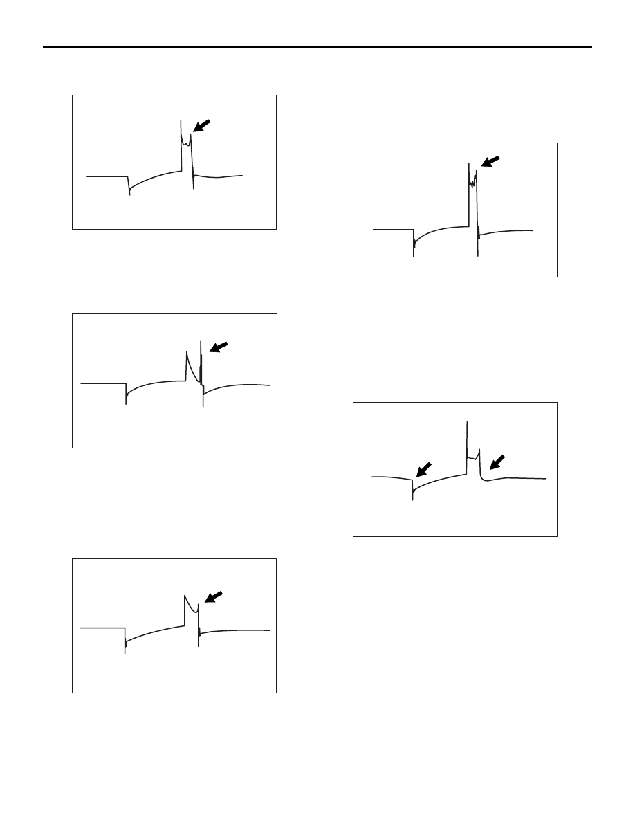
EXAMPLES OF ABNORMAL WAVE-
FORMS

AKX00280

Example 1

• Wave characteristics

Spark line is high and short.

• Cause of problem

Spark plug gap is too large.

AKX00281

Example 2

• Wave characteristics

Spark line is low and long, and is sloping.
Also, the second half of the spark line is distorted. 

This could be a result of misfiring.

• Cause of problem

Spark plug gap is too small.

AKX00282

Example 3

• Wave characteristics

Spark line is low and long, and is sloping. How-

ever, there is almost no spark line distortion.

• Cause of problem

Spark plug gap is fouled.

AKX00283

Example 4

• Wave characteristics

Spark line is high and short.
Difficult to distinguish between this and abnormal 

waveform example 1.

• Cause of problem

Spark plug cable is nearly falling off (Causing a 

dual ignition).

AKX00284

Example 5

• Wave characteristics

No waves in wave damping section.

• Cause of problem

Layer short in ignition coil.

IGNITION SYSTEM

ENGINE ELECTRICAL

16-34

IGNITION COIL

REMOVAL AND INSTALLATION

M1163004000909

Pre-removal and Post-installation Operation
• Rocker Cover Centre Cover Removal and Installation 

(Refer to GROUP 11A, Camshaft and Valve Stem Seal 

P.11A-17

).

AC210297

1

1

4

2

3

4

10 ± 2 N·m

25 ± 4 N·m

AB

5

Removal steps 

1.

Ignition coil connectors

2.

Spark plug cable No. 1

3.

Spark plug cable No. 3

4.

Ignition coils

5.

Spark plugs

Removal steps (Continued)

IGNITION SYSTEM

ENGINE ELECTRICAL

16-35

CAMSHAFT POSITION SENSOR

REMOVAL AND INSTALLATION

M1163003400829

AC407255
AC505000

4

1

2

6

5

N

AB

3

N

10.5 ± 0.5 N·m

10.5 ± 0.5 N·m

Removal steps <exhaust side> 

1.

Camshaft position sensor 
connector

2.

Camshaft position sensor

3.

O-ring

Removal steps <inlet side> 

4.

Camshaft position sensor 
connector

5.

Camshaft position sensor

6.

O-ring

IGNITION SYSTEM

ENGINE ELECTRICAL

16-36

CRANK ANGLE SENSOR

REMOVAL AND INSTALLATION

M1163004800143

CAUTION

If the vehicle is equipped with the Brembo

 disc brake, during maintenance, take care not to contact 

the caliper with tool or parts, because the caliper paint will be scratched.

Pre-removal and Post-installation Operation
• Timing Belt Removal and Installation (Refer to GROUP 

11A,Timing Belt 

P.11A-36

).

• Radiator Reserve Tank Assembly Removal and Installa-

tion (Refer to GROUP 14, Radiator 

P.14-24

).

AC210409

1

5

6

AB

2

22 ± 4 N·m

22 ± 4 N·m

3

4

40 ± 5 N·m

22 ± 4 N·m

12 ± 2 N·m

12 ± 2 N·m

49 ± 9 N·m

49 ± 9 N·m

8.8 ± 1.0 N·m

Removal steps 

1.

Power steering pressure switch 
connector

2.

Power steering oil pump heat 
protector

<<

A

>>

3.

Power steering oil pump, bracket 
and oil reservoir assembly

4.

Power steering oil pump bracket

5.

Crank angle sensor connector

6.

Crank angle sensor

Removal steps (Continued)


Content   ..  352  353  354  355   ..