Mitsubishi Lancer Evolution IX. Manual - part 326
 

  Index      Mitsubishi     Mitsubishi Lancer Evolution IX - service repair manual


Search            


Content   ..  324  325  326  327   ..


Mitsubishi Lancer Evolution IX. Manual - part 326


AC100273

MB991621 

AF

POWER STEERING GEAR BOX AND LINKAGE

POWER STEERING

37-29

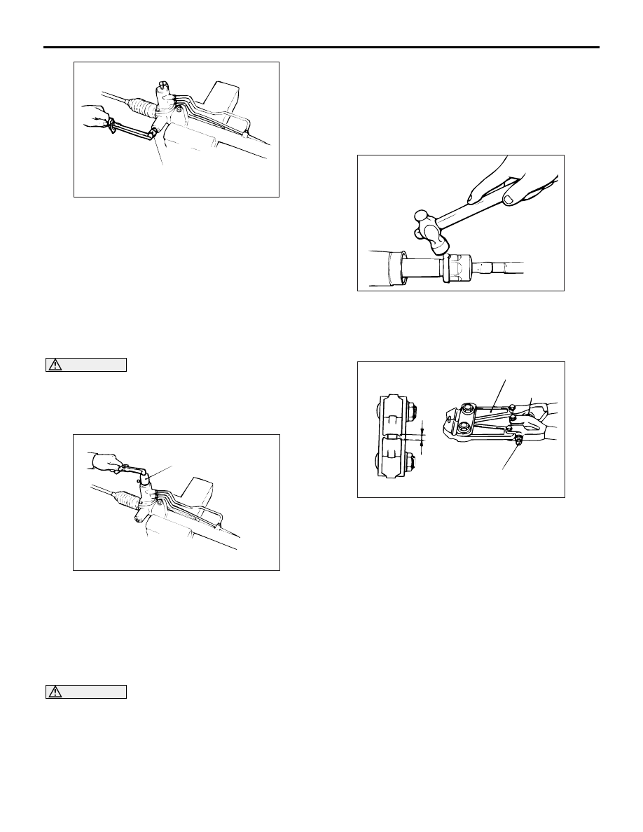
3. Use the following special tool piston driver 

(MB991621) to tighten the rack support cover to 
23 

± 2 N⋅m.

4. Turn the rack support cover 30

° anticlockwise.

5. Use the special tool to hold the rack support 

cover, and then tighten the lock nut to 59 

± 10 

N

⋅m.

>>K<< TOTAL PINION TORQUE 
ADJUSTMENT

CAUTION

• Be sure there is no ratcheting or catching 

when operating the rack towards the shaft.

AC100274AB

MB991006

Measure the total pinion torque through the 
whole stroke of the rack.

1. Using special tool preload socket (MB991006), 

rotate the pinion shaft at the rate of one rotation in 
4 to 6 seconds to check the total pinion torque and 
the change in torque.

Standard value:

Total pinion torque: 0.8 

 1.8 Nm  

Torque fluctuation: 0.49 N

m or less

CAUTION

When adjusting, set at the highest value of the 
standard value range.

NOTE: If the total pinion toque cannot be adjusted 
to the standard value within the specified return 
angle, check the rack support cover components 
and replace any parts if necessary.

2. If the total pinion torque or the change in torque is 

outside the standard value, move the rack support 
cover 0 

− 30°, and adjust the pinion torque again.

>>L<< TAB WASHER/TIE ROD 
INSTALLATION

ACX01163 AB

After installing the tie rod to the rack, fold tab washer 
end (two locations) to tie rod notch.

>>M<< BELLOWS BAND INSTALLATION

ACX01164 AB

W

MB991561

Adjusting bolt

Stopper

1. Turn the adjusting bolt of special tool boot band 

crimping tool (MB991561) to adjust the opening 
dimension (W) to the standard value.
NOTE: The dimension (W) is adjusted by approxi-
mately 0.7 mm per one turn.
NOTE: Do not turn the adjusting bolt more than 
one turn.

Standard value (W): 2.9 mm
<When more than 2.9 mm>: Screw in the 
adjusting bolt.
<When less than 2.9 mm>: Loosen the 
adjusting bolt.

POWER STEERING GEAR BOX AND LINKAGE

POWER STEERING

37-30

CAUTION

• Hold the rack housing, and use special tool to 

crimp the bellows band securely.

ACX01165 AB

MB991561

Crimp the bellows band until special tool 
touches the stopper.

2. Use special tool boot band crimping tool 

(MB991561) to crimp the bellows band.

ACX01166 AB

A

3. Check that crimped width (A) is within the 

standard value.

Standard value (A): 2.4 

 2.8 mm

<When more than 2.8 mm>: Readjust the 
dimension (W) of step (1) to the value calcu-
lated by the following equation, and repeat 
step (2).
 W = 5.5 mm 

 A [Example: if (A) is 2.9 mm, 

(W) is 2.6 mm.]
<When less than 2.4 mm>: Remove the bel-
lows band, readjust the dimension (W) of 
step (1) to the value calculated by the follow-
ing equation, and use a new bellows band to 
repeat steps (2) to (3).
W = 5.5 mm 

 A [Example: if (A) is 2.3 mm, 

(W) is 3.2 mm.]

>>N<< TIE ROD END/LOCK NUT 

INSTALLATION

AC001011AO

Lock nut

Edge of bellows
assembly groove

184 mm

Screw in the tie rod end to achieve the right and left 
length as illustrated. Lock with the lock nut.
NOTE: The lock nuts must be tightened securely 
only after the steering gear is installed to the vehicle 
and toe-in is adjusted.

>>O<< GEAR MOUNTING RUBBER 

INSTALLATION

AC100275AB

220 mm

Install the gear mounting rubber to the rack housing 
so that the distance is as shown in the illustration.

TIE ROD END BALL JOINT DUST COVER 

REPLACEMENT

M1372008200327

If the dust cover is damaged accidentally during 
service work, replace the dust cover as follows:

AC001012AB

MB990776

1. Apply specified grease to the lip and inside of the 

dust cover.

Specified grease:
Multipurpose grease SAE J310, NLGI No.2 or 
equivalent

POWER STEERING OIL PUMP ASSEMBLY

POWER STEERING

37-31

2. Drive in the dust cover with special tool front axle 

base (MB990776) until it is fully seated.

3. Check the dust cover for cracks or damage by 

pushing it with your finger.

POWER STEERING OIL PUMP ASSEMBLY

REMOVAL AND INSTALLATION

M1372005200470

Pre-removal Operation
• Power Steering Fluid Draining (Refer to 

P.37-10

).

Post-installation Operation
• Power Steering Fluid Supplying and Bleeding (Refer to 

P.37-10

).

• Drive Belt Tension Check (Refer to GROUP 11A, On-vehi-

cle Service 

− Drive Belt Tension Check 

P.11A-7

).

AC211828 AE

40 ± 5 N·m

8

7

1

2

3

4

6

40 ± 5 N·m*

18 ± 3 N·m

22 ± 4 N·m

5

N

22 ± 4 N·m

22 ± 4 N·m*

5

N

Removal steps 

1.

Pressure switch connector

2.

Drive belt (Refer to GROUP 
11A,Crankshaft Pulley 

P.11A-15

).

>>

B

<< 3.

Suction hose connection

>>

B

<< 4.

Pressure hose connection

>>

A

<< 5.

O-ring

6.

Heat protector

7.

Oil pump assembly

8.

Power steering pump bracket

Removal steps (Continued)

POWER STEERING OIL PUMP ASSEMBLY

POWER STEERING

37-32

INSTALLATION SERVICE POINTS
>>A<< O-RING INSTALLATION

AC311013

1

2

AB

No.

ID 

× Width mm

1

11.0 

× 1.9

2

13.0 

× 1.9

>>B<< PRESSURE HOSE 
ASSEMBLY/SUCTION HOSE REMOVAL

AC211830 AC

Suction hose

Marking

Pressure hose 
assembly

Notch

Install the pressure hose assembly and suction hose 
as illustrated.

DISASSEMBLY AND REASSEMBLY

M1372005400418

AC211831

21 ± 3 N·m

2

3

1

39 ± 5 N·m

4

: Automatic transmission fluid DEXRON or DEXRON II

N

AC

Removal steps 

1.

Suction connector

2.

O-ring

3.

Connector

4.

Gasket

INSPECTION 

M1372005500277

• Check the drive belt for cracks.

• Check the pulley for uneven rotation.


Content   ..  324  325  326  327   ..