Mitsubishi Lancer Evolution IX. Manual - part 322
 

  Index      Mitsubishi     Mitsubishi Lancer Evolution IX - service repair manual


Search            


Content   ..  320  321  322  323   ..


Mitsubishi Lancer Evolution IX. Manual - part 322


STEERING WHEEL

POWER STEERING

37-13

4. Hold the one way capsule as shown, and then try 

to lock them. If there is a slack in either of the 
capsules, replace the steering column shaft 
assembly.
NOTE: When installing a new steering column 
shaft assembly, place the tilt lever in the lock posi-
tion, if it is not in place.

CAUTION

• Be careful that nothing is pinched between 

the one-way capsules and the body.

• Do not release the tilt lever until the steering 

column has been installed to complete this 
inspection procedure.

5. If no problem is found during the inspection, 

tighten the steering column mounting bolts to the 
specified torque.

Tightening torque: 12 

± 2 Nm

STEERING WHEEL

REMOVAL AND INSTALLATION

M1372011400279

WARNING

Before removing the steering wheel and air bag module assembly, refer to GROUP 52B, 
Service Precautions (

P.52B-3

) and Air Bag Module and Clock Spring (

P.52B-110

).

Post-installation Operation
• Checking Steering Wheel Position with Wheels Straight 

Ahead

AC211760AD

50 ± 5 N·m

2

1

2

Removal steps 

<<

A

>>

1. Cover

<<

B

>>

2. Steering wheel and air bag module 

assembly

When removing and installing the steering wheel, do not let it bump against the air bag 
module.

STEERING WHEEL

POWER STEERING

37-14

REMOVAL SERVICE POINTS
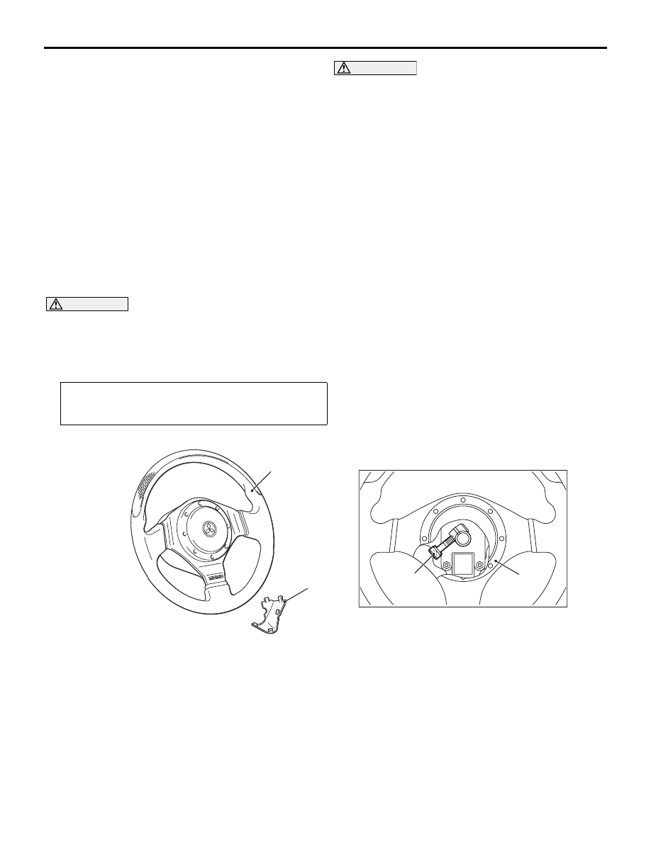
<<A>> COVER REMOVAL

AC211761AB

MB990784

Insert special tool ornament remover (MB990784) at 
the indicated position to remove the cover.
NOTE: The special tool can be inserted through the 
notch behind the area shown.

<<B>> STEERING WHEEL AND AIR BAG 
MODULE ASSEMBLY REMOVAL

AC105823

AC304700

AC305145AB

A

Steering
wheel

Air bag module 
connector

1. By sliding section A of the clock spring connector 

as shown in the illustration in the arrow direction, 
disconnect the connector.

AC211762 AC

Hexagonal bit
socket

2. Loosen the bolt completely. Then, remove the 

steering wheel and air bag module assembly.
NOTE: Use a hexagonal bit socket or a hexagonal 
wrench having an effective length of 75 mm or 
more in the hexagonal section and the diameter of 
8 mm or more.

STEERING COLUMN SHAFT ASSEMBLY

POWER STEERING

37-15

STEERING COLUMN SHAFT ASSEMBLY

REMOVAL AND INSTALLATION

M1372003100091

WARNING

Before removing the steering wheel and air bag module assembly, refer to GROUP 52B, Serv-
ice Precautions (

P.52B-3

) and Air Bag Module and Clock Spring (

P.52B-110

).

Pre-removal Operation
• Steering Wheel and Air bag Module Assembly Removal 

(Refer to 

P.37-13

).

• Under Cover Removal (Refer to GROUP 52A, Instrument 

Panel 

P.52A-2

).

Post-installation Operation
• Under Cover Installation (Refer to GROUP 52A, Instru-

ment Panel 

P.52A-2

).

• Steering Wheel and Air bag Module Assembly Installation 

(Refer to 

P.37-13

).

AC310967AB

12 ± 2 N·m

18 ± 2 N·m

5.0 ± 1.0 N·m

1

2

3

2

1

6

A

A

Tab

Section A - A

Section B - B

B

B

Toe board

Specified sealant: 
    3M ATD Part No.8513 or equivalent

B

B

4

5

(mounting screw)

2.5 ± 0.5 N·m

6

Removal steps 

1. Lower column cover
2. Upper column cover
3. Clock spring and column switch 

assembly (Refer to GROUP 52B, 
Driver’s, Front Passenger’s Air Bag 
Modules and Clock Spring 

P.52B-110

).

4. Shaft cover

<<

A

>> >>

A

<< 5. Steering column shaft assembly

6. Cover assembly

Removal steps (Continued)

STEERING COLUMN SHAFT ASSEMBLY

POWER STEERING

37-16

REMOVAL SERVICE POINT
<<A>> STEERING COLUMN SHAFT 
ASSEMBLY REMOVAL

CAUTION

The tilt lever should be held in the lock position 
until the steering column shaft is installed to the 
vehicle. If the steering column is removed with 
the tilt lever released, or the tilt lever is released 
after the steering column shaft was removed 
from the vehicle, the steering column can not be 
reinstalled correctly. If the steering column is 
installed incorrectly, the collision energy absorb-
ing mechanism may be damaged.
1. Ensure that the tilt lever is in the lock position, and 

remove the steering column mounting bolts.

AC210969AD

Clip

Steering column 
shaft

2. Pinch the steering column shaft clip with pliers, 

and pull up the shaft towards the direction shown 
to disengage the steering column shaft assembly.

INSTALLATION SERVICE POINT
>>A<< STEERING COLUMN SHAFT 
ASSEMBLY INSTALLATION

CAUTION

• When reusing the steering column, do not 

release the tilt lever until the steering column 
shaft has been installed.

• When the steering column is replaced, do not 

release the tilt lever until it has been installed. 
Do not remove the tilt lever fixing band until 
the installation has completed.

• When installing the steering column, do not 

leave it fixed temporarily at only one point 
and make sure the column shaft is not shaken 
strongly. If you fail to do, the collision absorb-
ing mechanism at the column shaft mounting 
location may be damaged.

AC209383AG

1

4

3

2

Tilt lever

Ensure that the tilt lever is in the lock position, and 
install the steering column. Tighten the four bolts in 
the order shown by hand, and then tighten them to 
the specified torque in the order shown.

Tightening torque: 12 

± 2 Nm


Content   ..  320  321  322  323   ..