Mitsubishi Lancer Evolution IX. Manual - part 317
 

  Index      Mitsubishi     Mitsubishi Lancer Evolution IX - service repair manual


Search            


Content   ..  315  316  317  318   ..


Mitsubishi Lancer Evolution IX. Manual - part 317


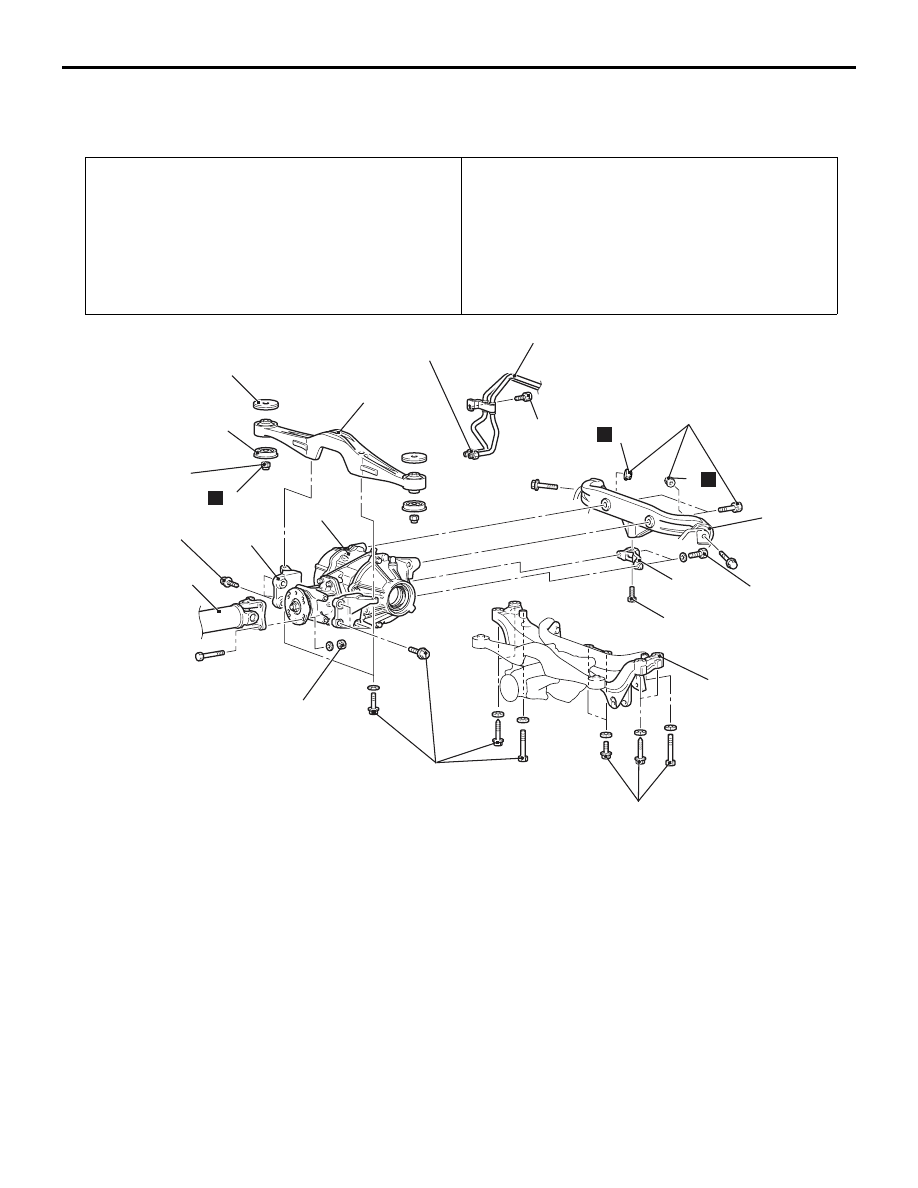
DIFFERENTIAL CARRIER ASSEMBLY

REAR AXLE

27-43

DIFFERENTIAL CARRIER ASSEMBLY

REMOVAL AND INSTALLATION

M1272002000522

Pre-removal Operation
• Hydraulic Piping Fluid Draining
• Differential Gear Oil Draining (Refer to 

P.27-27

).

• Lower Arm Assembly Removal (Refer to GROUP 34, 

Lower Arm Assembly and Assist Link 

P.34-12

 ).

• Rear Stabilizer Bar Removal (Refer to GROUP 34, Stabi-

lizer Bar 

P.34-20

).

• Driveshaft Removal (Refer to 

P.27-36

).

Post-installation Operation
• Driveshaft Installation (Refer to 

P.27-36

).

• Rear Stabilizer Bar Installation (Refer to GROUP 34, Sta-

bilizer Ba

P.34-20

).

• Lower Arm Assembly Installation (Refer to GROUP 34, 

Lower Arm Assembly and Assist Link 

P.34-12

 ).

• Differential Gear Oil Filling (Refer to 

P.27-27

).

• Hydraulic Piping Fluid Filling (Refer to 

P.27-27

).

• Hydraulic Piping Bleeding (Refer to 

P.27-28

).

AC310800AC

12 ± 2 N·m

88 ± 10 N·m

7

11

2

4

5

6

88 ± 10 N·m

44 ± 10 N·m

9

8

8

N

N

88 ± 10 N·m

1

21 ± 3 N·m

120 ± 10 N·m

3

N

10

88 ± 10 N·m

32 ± 2 N·m

88 ± 10 N·m

12

Removal steps 

1. Hydraulic unit hose assembly 

connection

<<

A

>> >>

C

<< 2. Propeller shaft connection (Refer to 

GROUP 25, Propeller shaft 

P.25-3

).

3. Differential support member mounting 

nut

<<

B

>> >>

B

<< 4. Rear crossmember and differential 

carrier assembly

5. Differential support member

>>

A

<< 6. Upper stopper

>>

A

<< 7. Lower stopper

8. Differential support arm mounting nut
9. Differential support arm
10. Differential mount bracket
11. Differential mount bracket
12. Differential carrier assembly

Removal steps (Continued)

DIFFERENTIAL CARRIER ASSEMBLY

REAR AXLE

27-44

REMOVAL SERVICE POINTS
<<A>> PROPELLER SHAFT DISCONNEC-
TION

AC003833

Mating marks

AC

1. Make mating marks on the differential companion 

flange and the propeller shaft assembly.

2. Suspend the removed propeller shaft from the 

body with a wire to prevent bending.

<<B>> REAR CROSSMEMBER AND 
DIFFERENTIAL CARRIER ASSEMBLY 
REMOVAL

1. Using a jack, support the differential carrier from 

its underside.

2. Remove the rear crossmember mounting bolts 

and remove the differential carrier, where it is 
attached to the rear crossmember, from the 
vehicle.

INSTALLATION SERVICE POINTS
>>A<< LOWER STOPPER/UPPER STOP-
PER INSTALLATION

AC310796 AB

Upper stopper

Lower stopper

Install the lower and upper stopper as shown in the 
illustration.

>>B<< REAR CROSSMEMBER AND 
DIFFERENTIAL CARRIER ASSEMBLY 
INSTALLATION

AC212040 AC

Front of vehicle

3

1

4

5

4

2

3

Tighten the rear crossmember mounting bolts in the 
numerical order shown.
NOTE: To ensure both good installation accuracy 
and ease of installation, the rear crossmember 
mounting holes have different diameters between 
front and rear. This is the reason for specifying the 
tightening sequence of the mounting bolts.

No.

Bolt type

Bolt size (Thread dia. 
× length) mm

1, 2, 
3

Flange bolt (with 
washer)

12 

× 105

4

Bolt (with spring 
washer and washer)

12 

× 152

5

Flange bolt (with 
washer)

12 

× 80

>>C<< PROPELLER SHAFT 
INSTALLATION

Align the mating marks of differential companion 
flange and propeller shaft assembly.

DIFFERENTIAL CARRIER ASSEMBLY

REAR AXLE

27-45

DIFFERENTIAL SUPPORT MEMBER 
BUSHING REPLACEMENT

M1272001400107

<DIFFERENTIAL MOUNT BRACKET>

AC212041

MB990641

Bushing

Differential
mount
bracket

Hollow

AB

1. Use special tool lower arm bush (A) remover and 

installer (MB990641) to remove or install the 
bushing.

2. Press-fit the bushing with its hollow portion facing 

in the direction shown.

3. Press-fit the bushing until the bushing outer case 

end face is flush with the differential mount 
bracket.

<DIFFERENTIAL SUPPORT ARM>

AC212059AB

MB991439

Bushing

Differential
support
arm

1. Use special tool bush remover and installer 

(MB991439) to remove the bushing.

AC212042

MB991439

Bushing

Differential
support arm

Hollow

AB

2. Press-fit the bushing with its marks facing in the 

direction shown.

3. Press-fit the bushing until the bushing outer case 

end face is flush with the differential support arm.

DIFFERENTIAL CARRIER ASSEMBLY

REAR AXLE

27-46

DISASSEMBLY AND REASSEMBLY

M1272008200018

AC310833 AB

9 ± 1 N·m

8

7

10

11

9

1

2

3

4

5

N

6

12

13

14

49 ± 10 N·m

N

N

N

N

N

186 ± 29 N·m

49 ± 10 N·m

4

N

49 ± 10 N·m

5 ± 1 N·m

N

3

Disassembly steps 

1. Drain plug
2. Packing
3. Filler plug
4. Gasket
5. Vent plug
6. Bleeder screw
7. Cover

<<

A

>> >>

C

<< 8. Self-locking nut

9. Washer
10. Companion flange
11. Oil seal

>>

B

<< 12. Oil seal

>>

A

<< 13. Oil seal

14. Differential carrier assembly

Disassembly steps (Continued)


Content   ..  315  316  317  318   ..