Mitsubishi Lancer Evolution IX. Manual - part 314
 

  Index      Mitsubishi     Mitsubishi Lancer Evolution IX - service repair manual


Search            


Content   ..  312  313  314  315   ..


Mitsubishi Lancer Evolution IX. Manual - part 314


ON-VEHICLE SERVICE

REAR AXLE

27-31

NOTE: To retain a space for removing the hub 
bolts, remove near the retainer spring mounting 
position.

AC001183

MB990767

AB

Plain
washer

3. Install the plain washer to the new hub bolt, and 

install the bolt with a nut.

DIFFERENTIAL CARRIER OIL SEAL 
REPLACEMENT

M1272001300133

DIFFERENTIAL PART

1. Remove the driveshaft from the differential carrier. 

(Refer to 

P.27-36

).

2. Remove the differential carrier oil seal.

AC102740

MB990938

MB991115

AC

3. Use the following special tools to press-fit a new 

oil seal.

• Installer bar (MB990938)

• Oil seal installer (MB991115)

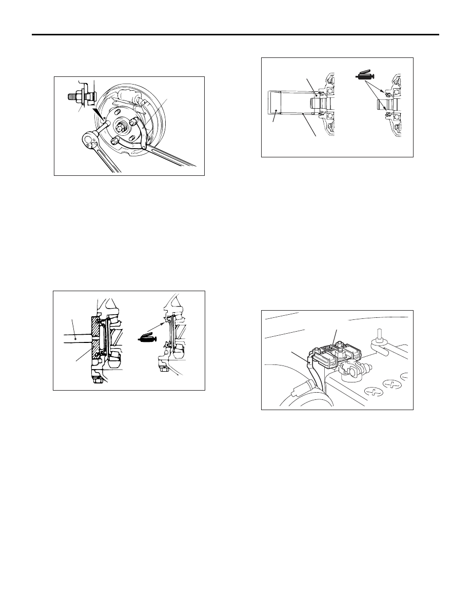
4. Apply multi-purpose grease to the oil seal lip and 

driveshaft oil seal seating area.

5. Replace the driveshaft circlip with a new one, and 

install the driveshaft to the differential carrier. 
(Refer to 

P.27-36

).

TORQUE TRANSFER MECHANISM PART

1. Remove the driveshaft from the differential carrier. 

(Refer to 

P.27-36

).

2. Remove the differential carrier oil seal.

AC310759AB

MD998829

MD998813

MD998812

3. Use the following special tools to press-fit a new 

oil seal.

• Installer cap (MD998812)

• Installer 100 (MD998813)

• Installer adaptor (MD998829)

4. Apply specified grease to the oil seal lip and 

driveshaft oil seal seating area.

Specified grease: Vaseline

5. Replace the driveshaft circlip with a new one, and 

install the driveshaft to the differential carrier. 
(Refer to 

P.27-36

).

REMEDY FOR A DISCHARGED BATTERY

M1272005100023

AC310768 AB

Battery cable
for AYC

Battery fuse assembly

When the engine is started using a booster cable 
where the battery has completely run down and you 
attempt to start the vehicle without waiting for the 
battery to recover a certain charge, the engine can 
misfire and you just cannot start to move it. In such 
cases, charge the battery sufficiently; or, remove the 
AYC battery cable from the battery fuse assembly to 
make AYC inactive before attempting to start the 
vehicles. When the battery cable is removed, the 
ACD mode indicator lamp lights up. After the battery 
has been recharged, fit the battery cable back again 
and start the engine to ensure that the ACD mode 
indicator lamp is off.

REAR AXLE HUB ASSEMBLY

REAR AXLE

27-32

REAR AXLE HUB ASSEMBLY

REMOVAL AND INSTALLATION

M1271002000466

CAUTION

• Do not strike the ABS rotors installed to the EBJ outer race of driveshaft against other parts when 

removing or installing the driveshaft. Otherwise the ABS rotors will be damaged.

• Be careful not to strike the pole piece at the tip of the rear ABS sensor with tools during servicing 

work.

Pre-installation Operation

• Gear Oil Draining (Refer to 

P.27-26

).

Post-installation Operation

• Gear Oil Filling (Refer to 

P.27-26

).

• Parking Brake Lever Stroke Adjustment (Refer 

to GROUP 36, On

−vehicle Service − Parking 

Brake Lever Stroke Check 

P.36-3

).

AC211950 AC

225 ± 25 N·m

8

7

10

11

9

2

3

4

5

1

N

6

12

54 ± 5 N·m

118 ± 19 N·m

71 ± 7 N·m

Removal steps 

1. Split pin

<<

A

>> >>

A

<< 2. Driveshaft nut

>>

A

<< 3. Washer

4. Rear ABS sensor

<<

B

>>

5. Caliper assembly
6. Brake disc

7. Parking brake shoe and lining 

assembly (Refer to GROUP 36, 
Parking brake lining and drum 

P.36-6

).

8. Clip
9. Parking brake cable connection
10. Rear driveshaft assembly

<<

C

>>

11. Rear wheel hub assembly
12. Backing plate

During maintenance, take care not to contact the parts or tools to the caliper because the paint of 
caliper will be scratched. And if there is brake fluid on the caliper, wipe out quickly.

Removal steps (Continued)

REAR AXLE HUB ASSEMBLY

REAR AXLE

27-33

REMOVAL SERVICE POINTS
<<A>> DRIVESHAFT NUT REMOVAL

CAUTION

Do not apply pressure to the wheel bearing by 
the vehicle weight to avoid possible damage 
when the driveshaft nut is loosened.

AC205988

MB990767

AB

Use special tool front hub and end yoke holder 
(MB990767) to fix the hub and remove the driveshaft 
nut.

<<B>> CALIPER ASSEMBLY REMOVAL

CAUTION

During maintenance, take care not to contact the 
parts or tools to the caliper because the paint of 
caliper will be scratched.
Secure the removed caliper assembly with wire, etc.

<<C>> REAR WHEEL HUB REMOVAL

If the rear wheel hub is seized, remove the rear 
wheel hub as follows.
1. Remove the knuckle with rear wheel hub and fix 

them with a vise (Refer to 

P.27-35

).

AC207000

AB

MB990211

MB991354

MB990244

2. Use the following special tools to pull out the rear 

wheel hub from the knuckle.

• Puller bar (MB990244)

• Puller body (MB991354)

• Slide hammer (MB990211)

INSTALLATION SERVICE POINT
>>A<< WASHER/ DRIVESHAFT NUT 
INSTALLATION

CAUTION

Before securely tightening the driveshaft nuts, 
make sure there is no load on the wheel bear-
ings. Otherwise the wheel bearings will be dam-
aged.

AC205992

AC

MB990767

Washer

1. Be sure to install the driveshaft washer in the 

specified direction.

2. Using special tool front hub and end yoke holder 

(MB990767), tighten the driveshaft nut to the 
specified torque.

Tightening torque: 225 

± 25 Nm

INSPECTION

M1271002100300

WHEEL BEARING ROTATION STARTING 
TORQUE AND AXIAL PLAY CHECK

AC212015 AB

MB991000

MB991017

1. Tighten the following special tools to the specified 

torque.

• Front hub remover and installer (MB991017)

• Spacer (MB991000)

Tightening torque: 225 

± 25 Nm

2. Rotate the rear hub in order to seat the bearing.

AC206090 AD

MB990326 Wooden

block

MB990685

Wooden
block

REAR AXLE HUB ASSEMBLY

REAR AXLE

27-34

3. Hold the rear wheel hub assembly with wooden 

blocks.

4. Measure the wheel bearing rotation starting 

torque by using the following special tools.

• Preload socket (MB990326)

• Torque wrench (MB990685)

Limit: 1.0 N

m

5. If the rotation starting torque is not within the limit 

range while the nut is tightened to 225 

± 25 N⋅m, 

replace the front wheel bearing assembly. If there 
are any signs of binding or tight spots when the 
wheel bearing turns, replace it.

AC206091AG

Wooden
block

Wooden
block

MB991017

6. Measure to determine whether the wheel bearing 

axial play is within the specified limit or not.

Limit: 0.05 mm

7. If the play is not within the limit range while the nut 

is tightened to 225 

± 25 N⋅m, replace the rear 

wheel hub assembly.


Content   ..  312  313  314  315   ..